

2 layers26 × 30 mm
Microcontroller
FrameworkComputer/ExpansionCards
Reference designs and documentation to create Expansion Cards for the Framework Laptop
34 parts1.1kCC-BY-4.0

It is a LoRa ( Long Range ) powered pocket off grid pager.
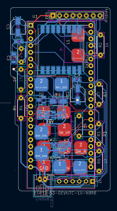
HUGINN is an open-source printed circuit board by basic-bitch-foundation, from the basic-bitch-foundation/HUGINN repository on GitHub. It is a 2-layer board of 37.9 × 69.1 mm with 35 parts on 58 nets, routed with 346 tracks and 2 vias.
It is built around the AP2112K-3.3. Its parts include 10 capacitors, 7 resistors, 5 switches, 2 ICs and 2 inductors. It belongs with the ESP32 boards of this library.
Huginn was crow of Odin (Greek God), He was messenger of hims. Thus this will be your personal messenger, let u communicate w/ hommies in any 9 realms.
It is a LoRa ( Long Range ) powered pocket off grid pager.
It have BOM, Custom PCB, 3D printed Enclosure, buttons and suport. Download All files(.stp) from Enclosure printable folder and print 'em
It uses M2 screw everywhere For part link please download .odf not .csv In assembly u may see the MCU as colliding with PCB dw! it just cz I can't remove the header pins. :lollll:
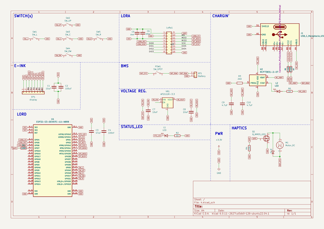
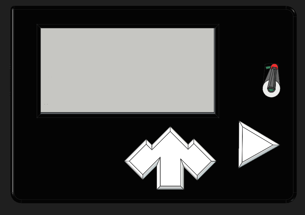
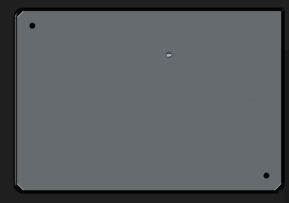
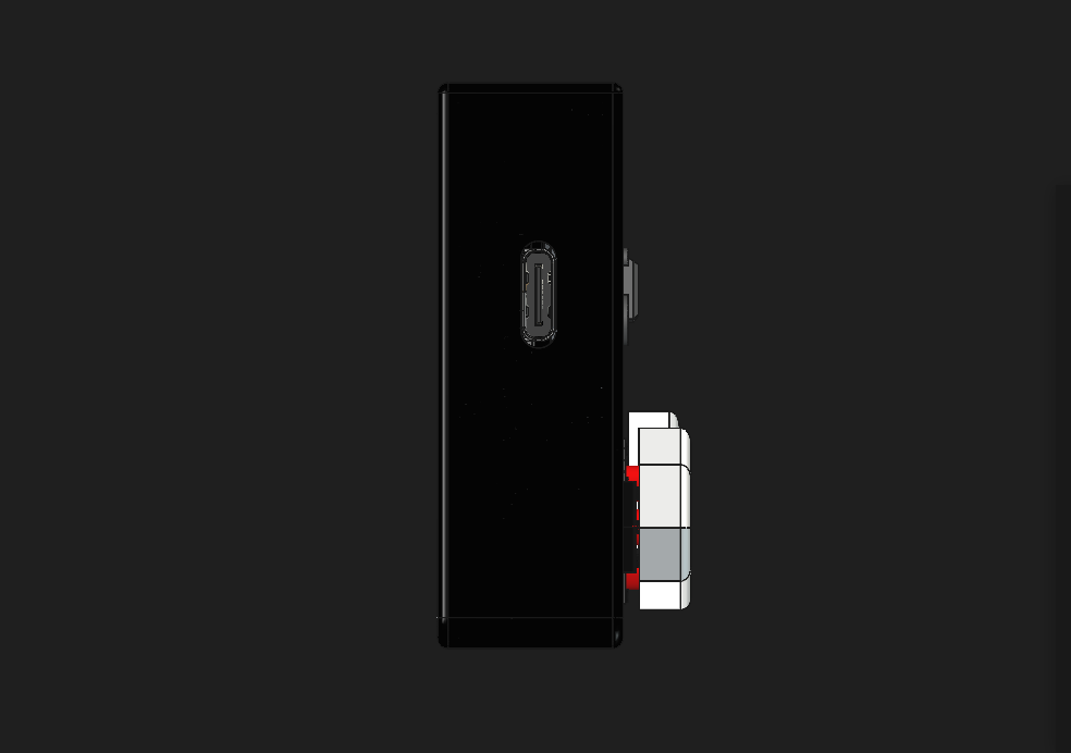
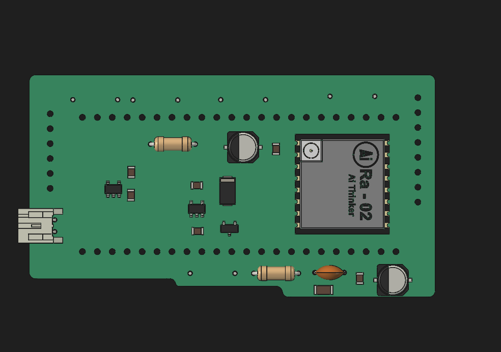
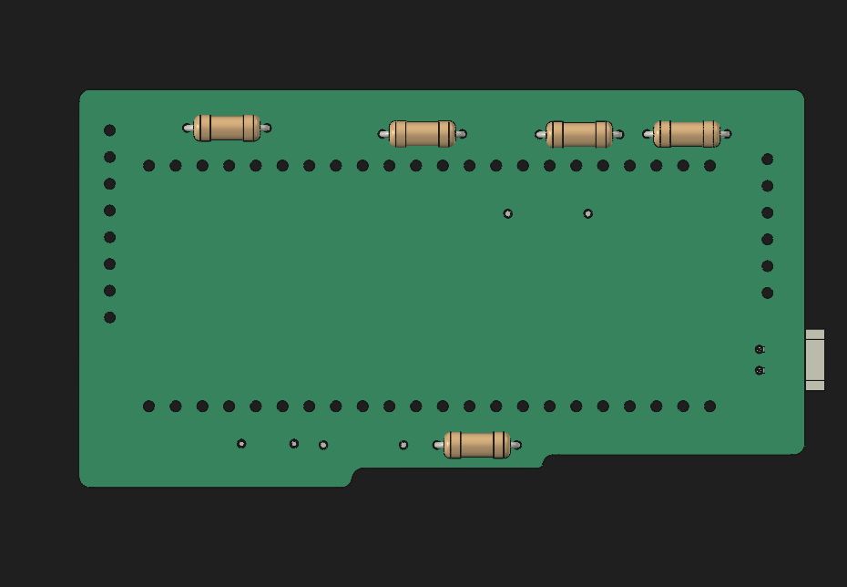
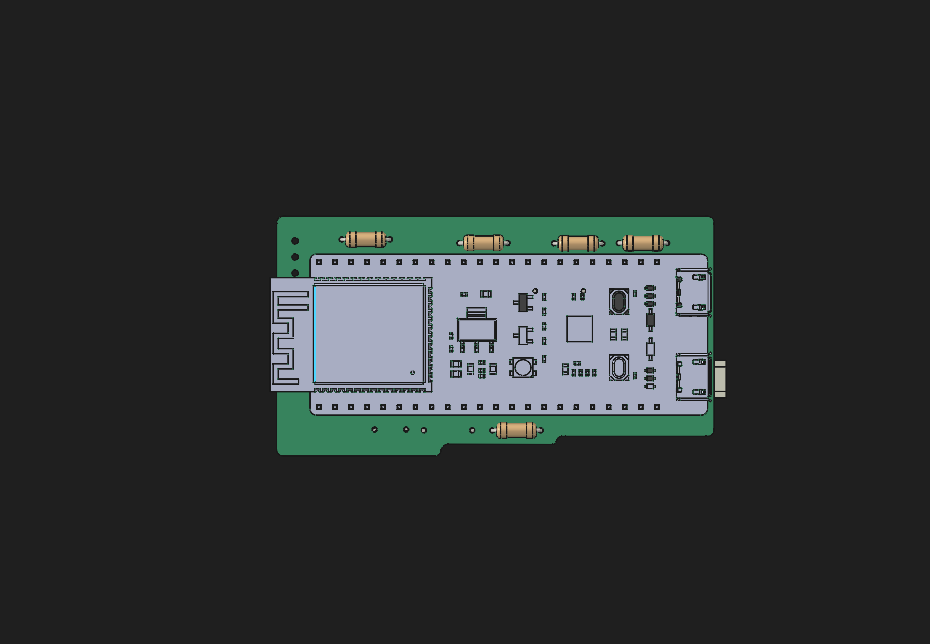
First comes the MCU U hve to castellated solder it on top of the board or can use very low height header pins
then Display as display I gave in BOM, Have 8 pin(Goes to HAT) to 8 , I will suggest to solder 'em direct , though half height n 2.54 header can use.
Stating with solder all component On PCB , As most part will be connected using wire to component to SMD solder Pad.
5 switches 2 LEDs Battery (optional)
The semi rotating switch have two part one is switch with rod dropped and a pad put the switch inside carv and then fix the pad on left face of rod so i can press momentary switch. Then, Screw it from bellow (Enough clamp so that It can't move freely but can move!)
As most part have support in Enclosure but gluing it make it smooth
Glue the disc motor that will send vibration through body
I don't gave the outing for LED cz It was ruining the Aesthetics of E ink's calm there so Any who want to see the charging status can place it nea usb input or a small hole behind panel
This is basic firmware code u can compile and flash it in MCU using Platform.io (a extension in VS code) or using Thonny (IDE)
As pager need to be quick I added three code fn! and a local converter: So U navigate up/down between 143 ( I Love u!) 505 ( SOS ) etc. the click the send button when reciver will reciver get it wil automaticall converted in their own device . This save the bytes of daya is trasmitting and saving time
I use like very little < 10% AI for code.
Made for Hackclub <3 by Saksham (A.K.A bbb) Feel free to contribute :heart:
| Qty | Value | Footprint | References |
|---|---|---|---|
| 3 | 10uF | Capacitor_SMD:C_0805_2012Metric | C1, C7, C8 |
| 2 | 100uF | Capacitor_SMD:CP_Elec_5x5.3 | C2, C6 |
| 2 | 1k | Resistor_THT:R_Axial_DIN0207_L6.3mm_D2.5mm_P7.62mm_Horizontal | R2, R6 |
| 2 | 4.7uF | Capacitor_SMD:C_0805_2012Metric | C9, C10 |
| 2 | 5.1kΩ | Resistor_THT:R_Axial_DIN0207_L6.3mm_D2.5mm_P7.62mm_Horizontal | R5, R7 |
| 2 | LED | solderwirepad_1_02_SMD:SolderWirePad_1x02_SMD_5x5mm | L1, L2 |
| 1 | 100nf | Capacitor_THT:C_Disc_D5.0mm_W2.5mm_P5.00mm | C4 |
| 1 | 100Ω | Resistor_THT:R_Axial_DIN0207_L6.3mm_D2.5mm_P7.62mm_Horizontal | R1 |
| 1 | 10k | Resistor_THT:R_Axial_DIN0207_L6.3mm_D2.5mm_P7.62mm_Horizontal | R4 |
| 1 | 10uf | Capacitor_SMD:C_0805_2012Metric | C5 |
| 1 | 2kΩ | Resistor_THT:R_Axial_DIN0207_L6.3mm_D2.5mm_P7.62mm_Horizontal | R3 |
| 1 | 47uF | Capacitor_SMD:C_1206_3216Metric | C3 |
| 1 | AP2112K-3.3 | Package_TO_SOT_SMD:SOT-23-5 | VR1 |
| 1 | Battery | Connector_JST:JST_PH_S2B-PH-K_1x02_P2.00mm_Horizontal | BT1 |
| 1 | D | Diode_SMD:D_SMA | D1 |
| 1 | ESP32-S3-DEVKITC-1U-N8R8 | ESP32-n8r8:ESP32-S3-DEVKITC-1-N8R8 | U1 |
| 1 | MCP73831-2-OT | Package_TO_SOT_SMD:SOT-23-5 | U2 |
| 1 | Motor_DC | solderwirepad_1_02_SMD:SolderWirePad_1x02_SMD_5x5mm | M1 |
| 1 | Q_NMOS_GDS | Package_TO_SOT_SMD:SOT-23 | Q1 |
| 1 | SW_C | solderwirepad_1_02_SMD:SolderWirePad_1x02_SMD_5x5mm | SW3 |
| 1 | SW_DW | solderwirepad_1_02_SMD:SolderWirePad_1x02_SMD_5x5mm | SW4 |
| 1 | SW_L | solderwirepad_1_02_SMD:SolderWirePad_1x02_SMD_5x5mm | SW1 |
| 1 | SW_R | solderwirepad_1_02_SMD:SolderWirePad_1x02_SMD_5x5mm | SW5 |
| 1 | SW_SPST | solderwirepad_1_02_SMD:SolderWirePad_1x02_SMD_5x5mm | PSW1 |
| 1 | SW_UP | solderwirepad_1_02_SMD:SolderWirePad_1x02_SMD_5x5mm | SW2 |
| 1 | USB_C_Receptacle_USB2.0 | Connector_PinSocket_2.54mm:PinSocket_1x06_P2.54mm_Vertical | J1 |
| 1 | display | Connector_PinHeader_2.54mm:PinHeader_1x08_P2.54mm_Vertical | EP1 |
| 1 | left | RA-02_LORA:MODULE_RA-02_LORA | LoRa1 |
It measures 37.9 × 69.1 mm and has 2 copper layers, 1.6 mm thick.
35 parts, built around the AP2112K-3.3. The full list of its parts is on this page, with links to each part's symbol and footprint where PCBKit's library has them.
From the basic-bitch-foundation/HUGINN repository on GitHub, at the commit this page was made from: the board is h/h.kicad_pcb and its schematic Schematic/h.kicad_sch. PCBKit opens the board in the browser, with nothing to install.
Its repository states no licence, so its author keeps all rights: ask basic-bitch-foundation before reusing the design.
FrameworkComputer/ExpansionCards
Reference designs and documentation to create Expansion Cards for the Framework Laptop


DDeGonge/OS-ARM
This arm is not industrial and it will not be fast, but that is not my goal. But it will hopefully be a very nice looking arm fully capable of 6dof motion, cheap enough to keep it accessable but capable enough to…


