2 layers26 × 23 mm

 bartkepl/SDT_board
Benchtop thermometer with SCPI and USB.
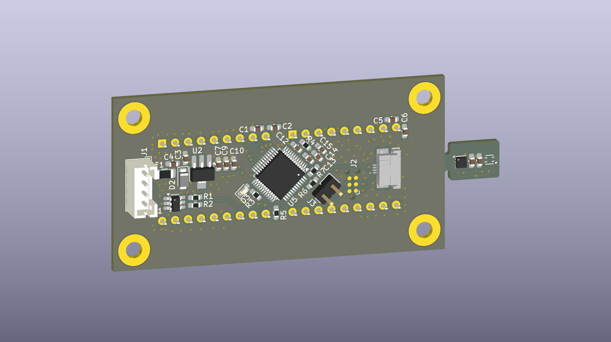
SDT board is an open-source printed circuit board by bartkepl, from the bartkepl/SDT_board repository on GitHub, published under the MIT licence. It is a 4-layer board of 75.7 × 34 mm with 41 parts on 56 nets, routed with 471 tracks and 167 vias.
It is built around the LDI1117-3.3U, USBLC6-2SC6 and HDLO-2416, with the SFV4R-3STBE1HLF and SMF5.0CA among its other parts. Its parts include 15 capacitors, 7 resistors, 5 ICs, 5 connectors and 4 diodes. It belongs with the sensors and measurement boards and the STM32 boards of this library.


Benchtop USB thermometer with a SCPI interface and an 8-character LED display, built around an STM32C071CBT6 (ARM Cortex-M0+). Measures temperature (and optionally humidity), shows it on the display, and exposes a full instrument control interface over USB.
📖 Full documentation: https://bartkepl.github.io/SDT_board/ (PL)
| Path | Contents |
|---|---|
pcb/ | KiCad project — schematic, layout, 3D models, fabrication jobsets |
prod/ | Production outputs — Gerbers, drill files, schematic/PCB PDFs, interactive BOM |
firmware/ | STM32C071 firmware (STM32CubeIDE project) — bundles TinyUSB + scpi-parser |
software/ | PC host app (Python/Tkinter) — SCPI GUI, plotting, CSV logging, DFU flashing |
doc/ | MkDocs documentation source (deployed to GitHub Pages) |
media/ | Board photos |
The firmware is an STM32CubeIDE project in firmware/USB-TMC_src/.
File → Open Projects from File System…).Project → Build All).SYSTem:DFU command
and the host app has a one-click flash helper).Vendored dependencies are included in-tree so the project builds without extra setup:
A desktop companion app lives in software/:
cd software
pip install -r requirements.txt
python main.py
It provides a live readout and plot, a SCPI console, sensor/display
configuration, CSV logging, and a DFU flashing helper. See
software/README.md for details.
You can also talk to the board from any VISA-capable environment:
import pyvisa
rm = pyvisa.ResourceManager('@py')          # VID=0xCAFE, PID=0x4000
inst = rm.open_resource('USB0::0xCAFE::0x4000::SDT_YOURHASH::INSTR')
print(inst.query('*IDN?'))
print(inst.query('SENSor:TEMPerature?'))The full hardware, firmware, and SCPI command reference is published at
https://bartkepl.github.io/SDT_board/ and authored in doc/
(MkDocs Material). Build it locally with:
pip install -r doc/requirements-docs.txt
mkdocs serve -f doc/mkdocs.ymlIdea based on SCPI Capable Thermometer.
Display part & footprint from kicad-intelligent-displays by 74hc595.
USB-TMC stack from TinyUSB. SCPI parser from scpi-parser by Jan Breuer.
Released under the MIT License. Open to contributions in both software and hardware!
| Qty | Value | Footprint | References |
|---|---|---|---|
| 15 | 100nF | Capacitor_SMD:C_0603_1608Metric_Pad1.08x0.95mm_HandSolder | C1, C2, C3, C4, C5, C6, C7, C9, C10, C11, C12, C13, C14, C15, C16 |
| 4 | MountingHole_Pad | MountingHole:MountingHole_3.2mm_M3_Pad | H1, H2, H3, H4 |
| 2 | 100K | Resistor_SMD:R_0603_1608Metric_Pad0.98x0.95mm_HandSolder | R4, R5 |
| 2 | 10k | Resistor_SMD:R_0603_1608Metric_Pad0.98x0.95mm_HandSolder | R6, R7 |
| 2 | 22R | Resistor_SMD:R_0603_1608Metric_Pad0.98x0.95mm_HandSolder | R1, R2 |
| 2 | HDLO-2416 | Display_IntelligentAlpha:DL2416 | D1, D4 |
| 2 | SFV4R-3STBE1HLF | SamacSys_Parts:SFV4R3STBE1HLF | J4, J5 |
| 1 | 2K | Resistor_SMD:R_0603_1608Metric_Pad0.98x0.95mm_HandSolder | R3 |
| 1 | Conn_01x02 | Connector_PinHeader_2.54mm:PinHeader_1x02_P2.54mm_Vertical | J3 |
| 1 | LDI1117-3.3U | Package_TO_SOT_SMD:SOT-89-3_Handsoldering | U2 |
| 1 | LED | LED_SMD:LED_0603_1608Metric_Pad1.05x0.95mm_HandSolder | D3 |
| 1 | Polyfuse | Fuse:Fuse_1206_3216Metric_Pad1.42x1.75mm_HandSolder | F1 |
| 1 | SHT4x | Sensor_Humidity:Sensirion_DFN-4_1.5x1.5mm_P0.8mm_SHT4x_NoCentralPad | U6 |
| 1 | SMF5.0CA | Diode_SMD:D_SMF | D2 |
| 1 | STM32C071CBTx | Package_QFP:LQFP-48_7x7mm_P0.5mm | U5 |
| 1 | TC2030 | Connector:Tag-Connect_TC2030-IDC-NL_2x03_P1.27mm_Vertical | J2 |
| 1 | TMP117xxDRV | Package_SON:WSON-6-1EP_2x2mm_P0.65mm_EP1x1.6mm | U4 |
| 1 | USBLC6-2SC6 | Package_TO_SOT_SMD:SOT-23-6_Handsoldering | U1 |
| 1 | USB_B | Connector_JST:JST_PH_B4B-PH-K_1x04_P2.00mm_Vertical | J1 |
It measures 75.7 × 34 mm and has 4 copper layers, 1.59 mm thick.
41 parts, built around the LDI1117-3.3U, USBLC6-2SC6, HDLO-2416 and SFV4R-3STBE1HLF. The full list of its parts is on this page, with links to each part's symbol and footprint where PCBKit's library has them.
From the bartkepl/SDT_board repository on GitHub, at the commit this page was made from: the board is pcb/SDT_board.kicad_pcb and its schematic pcb/SDT_board.kicad_sch. PCBKit opens the board in the browser, with nothing to install.
Its repository publishes it under the MIT licence: you may reuse it on that licence's terms (keep the author's notice, and for a copyleft licence share your changes alike).


atomicra1n/wifi-geiger-counter
A DIY Geiger counter PCB which can detect ionizing radiation and log readings over Wi-Fi. Built with an ESP32, and a HV multiplier circuit that steps up 3.7V to 400V for the GM tube.

bartkepl/RDE_board
Resistance DEcade with SCPI, UART, USB, RS485 and ETHERNET in 3U eurocard format

bartkepl/UCB_board
Control board for testing concepts with SCPI, UART, USB, RS485 and ETHERNET in pseudo 3U eurocard format

danhmanu/PLC-STM32F407VET6
Mạch nguyên lý KiCad 10 cho bộ PLC: điều khiển qua LAN bằng Modbus TCP (module W5500 Lite), nạp code qua USB‑C (CH340C), 16 ngõ ra transistor cách ly quang, 10 ngõ vào analog 4–20mA.
