

2 layers45.7 × 63.5 mm
Feuchtraumabzweigdose
transportkollektiv/feuchtraumabzweigdose
A custom GPS Tracker with LoRaWAN/TTN intended for use on a bicycle
40 parts14CC-BY-4.0

 barnabywalters/Schraeg43
An 8HP eurorack multimode filter module based on the Bastl Cinnamon
Schraeg is an open-source printed circuit board by barnabywalters, from the barnabywalters/Schraeg repository on GitHub, published under the CC-BY-SA-4.0 licence. It is a 2-layer board of 84.5 × 128.5 mm with 116 parts on 75 nets, routed with 833 tracks and 99 vias.
It is built around the PJ301M-12 and MB2S. Its parts include 49 resistors, 28 capacitors, 6 diodes, 5 ICs and 2 fuses. It belongs with the audio and music boards of this library.
Schräg is an 8HP multimode filter module for the eurorack format, based off the Bastl Cinnamon.
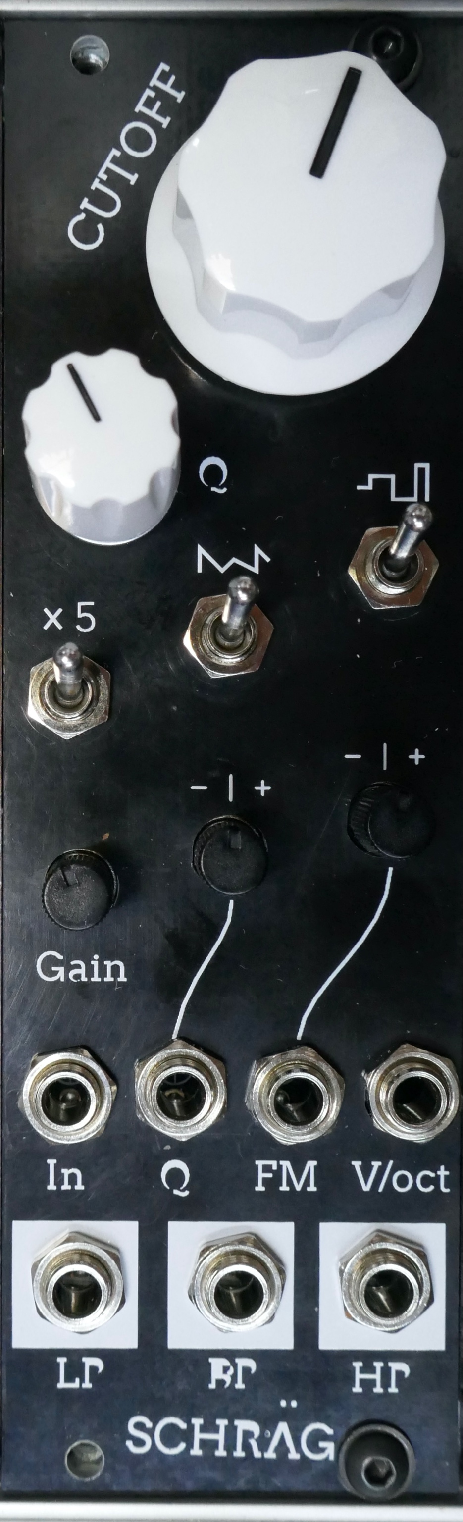
As of 2021-03-01, at least one person has reported successfully building the current board revision. However, another builder reported a minor issue with the attenuverter circuits which prevents full-range voltage control over resonance (and limits voltage control over FM). This should be fixable only with component substitutions, we’re working on a fix. More information and updates in the corresponding lines thread.
See the Changelog below for more updates and version-specific fixes.
I can’t promise quick responses, but am happy to try to help out!
If you’re having trouble or need help assembling or troubleshooting a Schräg, please start a discussion.
If you’ve found a specific error which needs fixing, please file an issue.
If you’re not sure which, start a discussion, and we’ll convert it into an issue if we can distill it into a concrete problem.
Schräg is effectively a repackaged Bastl Cinnamon:
with a few modifications:
Schraeg/Output/Interactive BOM.html once you’ve cloned the repo locally) to aid in part placementThe additional functionality is achieved with a minimum of extra components, thanks to the two unused VCA cells in the original design.
The schematic, board layout and graphics are released under a cc-by-sa license. Bastl Instruments generously gave their permission for me to release my rework of their module. They’re a cool company. Go check out their work!
In 2019 I was looking through the Bastl Cinnamon schematic and realised that it only uses two of the four available V2164D VCA cells.
At the time I needed PCB layout practise (and a filter module for my DIY eurorack!), so I ended up prototyping and building an 8HP version of cinnamon for myself which uses the two spare cells to implement voltage control over resonance, as well as a few other little additions listed above.
I called it “Schräg” because of both the angled panel design, the weird sounds possible with Bastl’s cool distortion circuits, and the strange way KiCAD mangled the panel graphics.
A bit more than a year after building the first Schräg, I finally got around to fixing the various small issues with the first board revision, and asking Bastl if they were okay with me open-sourcing the project. They were, and here we are.
| Qty | Value | Footprint | References |
|---|---|---|---|
| 16 | 100k | Resistor_SMD:R_0603_1608Metric_Pad1.05x0.95mm_HandSolder | R1, R2, R3, R4, R5, R6, R7, R8, R9, R10, R11, R12, R13, R16, R17, R20 |
| 10 | 100n | Capacitor_SMD:C_0603_1608Metric_Pad1.05x0.95mm_HandSolder | C19, C20, C21, C22, C23, C24, C25, C26, C27, C28 |
| 9 | 33k | Resistor_SMD:R_0603_1608Metric_Pad1.05x0.95mm_HandSolder | R27, R28, R29, R31, R33, R34, R35, R36, R38 |
| 7 | PJ301M-12 | Eurocad:PJ301M-12 | AUDIO_IN1, BP_OUT1, FM_IN1, HP_OUT1, LP_OUT1, RES_CV1, V_OCT_IN1 |
| 5 | 100K | Resistor_SMD:R_0603_1608Metric_Pad1.05x0.95mm_HandSolder | R37, R42, R45, R48, R49 |
| 5 | 100k | Eurocad:Alpha9mmPot | CUTOFF1, FM_ATTV1, INPUT_GAIN1, RES_ATTV1, RESONANCE1 |
| 4 | 10uF | Capacitor_SMD:CP_Elec_5x4.5 | C2, C4, C5, C6 |
| 4 | 470R | Resistor_SMD:R_0603_1608Metric_Pad1.05x0.95mm_HandSolder | R15, R30, R32, R39 |
| 4 | 560pF | Capacitor_SMD:C_0603_1608Metric_Pad1.05x0.95mm_HandSolder | C1, C7, C8, C12 |
| 4 | TL074 | Package_SO:SOIC-14_3.9x8.7mm_P1.27mm | U1, U2, U4, U5 |
| 4 | VAL** | Eurocad:MOUSEBITE1mm | MOUSEBITE1mm, MOUSEBITE1mm, MOUSEBITE1mm, MOUSEBITE1mm |
| 3 | 1K | Resistor_SMD:R_0603_1608Metric_Pad1.05x0.95mm_HandSolder | R23, R24, R25 |
| 3 | 220n | Capacitor_SMD:C_0603_1608Metric_Pad1.05x0.95mm_HandSolder | C14, C15, C18 |
| 3 | 220pF | Capacitor_SMD:C_0603_1608Metric_Pad1.05x0.95mm_HandSolder | C10, C11, C13 |
| 3 | SW_SPDT | Connector_PinHeader_2.54mm:PinHeader_1x03_P2.54mm_Vertical | SW_DRIVE1, SW_RES_DIST1, SW_WOBBLE1 |
| 2 | 100pF | Capacitor_SMD:C_0603_1608Metric_Pad1.05x0.95mm_HandSolder | C3, C9 |
| 2 | 15K | Resistor_SMD:R_0603_1608Metric_Pad1.05x0.95mm_HandSolder | R14, R40 |
| 2 | 22uF | Capacitor_SMD:CP_Elec_6.3x5.4 | C16, C17 |
| 2 | 47k | Resistor_SMD:R_0603_1608Metric_Pad1.05x0.95mm_HandSolder | R19, R22 |
| 2 | 6.8K | Resistor_SMD:R_0603_1608Metric_Pad1.05x0.95mm_HandSolder | R44, R47 |
| 2 | D_Small | Diode_SMD:D_SOD-123 | D1, D2 |
| 2 | LM4040DBZ-5 | Package_TO_SOT_SMD:SOT-23_Handsoldering | D4, D6 |
| 2 | Polyfuse | Fuse:Fuse_1206_3216Metric_Pad1.42x1.75mm_HandSolder | F1, F2 |
| 2 | Val** | Schraeg:Schraeg Panel Graphics Inkscape | Ref**, Ref** |
| 1 | 1.5K | Resistor_SMD:R_0603_1608Metric_Pad1.05x0.95mm_HandSolder | R41 |
| 1 | 100k | Potentiometer_THT:Potentiometer_Bourns_3296W_Vertical | RV_SAW_OCTAVE1 |
| 1 | 10k | Resistor_SMD:R_0603_1608Metric_Pad1.05x0.95mm_HandSolder | R21 |
| 1 | 22k | Resistor_SMD:R_0603_1608Metric_Pad1.05x0.95mm_HandSolder | R18 |
| 1 | 250K | Potentiometer_THT:Potentiometer_Bourns_3296W_Vertical | RES_ADJ1 |
| 1 | 3.3K | Resistor_SMD:R_0603_1608Metric_Pad1.05x0.95mm_HandSolder | R46 |
| 1 | 330K | Resistor_SMD:R_0603_1608Metric_Pad1.05x0.95mm_HandSolder | R26 |
| 1 | 470K | Resistor_SMD:R_0603_1608Metric_Pad1.05x0.95mm_HandSolder | R43 |
| 1 | 5K | Potentiometer_THT:Potentiometer_Bourns_3296W_Vertical | V_OCT_SCALE1 |
| 1 | 5V | Diode_SMD:D_SOD-123 | D3 |
| 1 | EURO_PWR_2x5 | Connector_PinHeader_2.54mm:PinHeader_2x05_P2.54mm_Vertical | PWR_IN1 |
| 1 | G*** | Schraeg:Schraeg Panel Graphics Inkscape | svg2mod |
| 1 | MB2S | Package_TO_SOT_SMD:TO-269AA | D5 |
| 1 | V2164 | Package_SO:SOIC-16_3.9x9.9mm_P1.27mm | U3 |
transportkollektiv/feuchtraumabzweigdose
A custom GPS Tracker with LoRaWAN/TTN intended for use on a bicycle


skunkforce/edgy_boards_legacy
small mostly single chip design bits with put_on_edge connectors


wgd-modular/utf-8-samplified
Arduino nano sample based 8-channel drum module


wgd-modular/utf-9-samplified
A standalone drum machine based on the bleep drum.

It measures 84.5 × 128.5 mm and has 2 copper layers, 1.6 mm thick.
116 parts, built around the PJ301M-12 and MB2S. The full list of its parts is on this page, with links to each part's symbol and footprint where PCBKit's library has them.
From the barnabywalters/Schraeg repository on GitHub, at the commit this page was made from: the board is Schraeg/Schraeg.kicad_pcb. PCBKit opens the board in the browser, with nothing to install.
Its repository publishes it under the CC-BY-SA-4.0 licence: you may reuse it on that licence's terms (keep the author's notice, and for a copyleft licence share your changes alike).