2 layers20.5 × 24.8 mm

 barbeque/pc8801mkII-vga10
PCB for getting VGA from a PC8801mkII
Pc8801mkII vga is an open-source printed circuit board by barbeque, from the barbeque/pc8801mkII-vga repository on GitHub. It is a 2-layer board of 41.3 × 33 mm with 8 parts on 19 nets, routed with 39 tracks and 0 vias.
Its parts include 3 capacitors and 3 resistors. It belongs with the retro computing and games boards of this library.
This is a video adapter I built to go from my 1984 NEC PC-8801mkII's 3-bit digital RGB-out port to a VGA monitor. If you have an SR or newer, you can (and should) just use analogue RGB to VGA adapters instead.
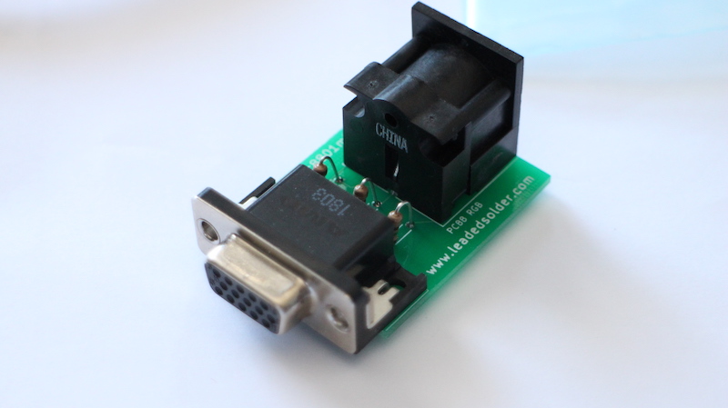
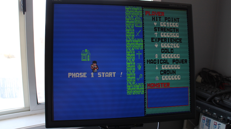
Please note that this is just a level shifter and pinout adapter. It is not a scan converter; if your monitor is not capable of 15kHz (or 24kHz for some machines) video, it will not work with this adapter. In other words, your monitor must match the output sync rate of the computer being adapted.
Please consult the 15kHz modern monitors list for models of monitor which may work with this adapter.
This board was developed as part of a project for the Leaded Solder blog. Chances are, if you have a computer that needs this adapter, you will probably enjoy the other projects on the blog too. Please consider backing the blog on Patreon to provide funds that will be used to make more open-source boards for the old-computer community.
WORKING, but improvements are likely to arrive in the coming days to deal with the "jailbar" interference pattern on some monitors.
You can use files from the gerber directory, the zip files in the Releases section, or order the board from the Shared Projects section of PCBway. Note that I receive a small PCBway credit for boards purchased through that platform.
| Qty | Value | Footprint | References |
|---|---|---|---|
| 3 | 0.1µF | Capacitor_THT:C_Disc_D3.4mm_W2.1mm_P2.50mm | C1, C2, C3 |
| 3 | 150Ω | Resistor_THT:R_Axial_DIN0207_L6.3mm_D2.5mm_P10.16mm_Horizontal | R1, R2, R3 |
| 1 | 15kHz VGA | Connector_TE_AMP_HD15:FIXED-1-1734530-1 | V1 |
| 1 | PC88 RGB | SDS-80J:CUI_SDS-80J | N1 |

joeycastillo/Sensor-Watch
A board replacement for the classic Casio F-91W wristwatch

rusefi/rusefi
rusefi - GPL internal combustion engine control unit

hoglet67/RGBtoHDMI
Bare-metal Raspberry Pi project that provides pixel-perfect sampling of Retro Computer RGB/YUV video and conversion to HDMI

shanteacontrols/OpenDeck
A platform for building interactive control and sensing devices using MIDI and OSC built with Zephyr RTOS.

hackclub/OnBoard
💡 Join 1,000 teenagers and make your first PCB with a $100 grant!

dangiu/PicoMemcard
Emulating PSX Memory Card (or controller) using a Raspberry Pi Pico

OLIMEX/DIY-LAPTOP
Do It Yourself Open Source Hardware and Software Modular Hacker's Friendly Laptop
It measures 41.3 × 33 mm and has 2 copper layers, 1.6 mm thick.
8 parts. The full list of its parts is on this page, with links to each part's symbol and footprint where PCBKit's library has them.
From the barbeque/pc8801mkII-vga repository on GitHub, at the commit this page was made from: the board is PC8801mkII VGA.kicad_pcb and its schematic PC8801mkII VGA.kicad_sch. PCBKit opens the board in the browser, with nothing to install.
Its repository states no licence, so its author keeps all rights: ask barbeque before reusing the design.