2 layers98 × 27 mm

 barbeque/floppy-edge-connector-adapter20
Adapt a floppy cable meant to use an edge connector to use a 34-pin female pin connector instead.
Floppy adapter-2 is an open-source printed circuit board by barbeque, from the barbeque/floppy-edge-connector-adapter repository on GitHub, published under the GPL-3.0 licence. It is a 2-layer board of 45.7 × 26.1 mm with 5 parts on 34 nets, routed with 98 tracks and 0 vias.
It belongs with the interfaces and adapters boards of this library.
This adapter is intended to allow older computers equipped with 5.25" floppy drives using an edge connector to use a 3.5" floppy drive.
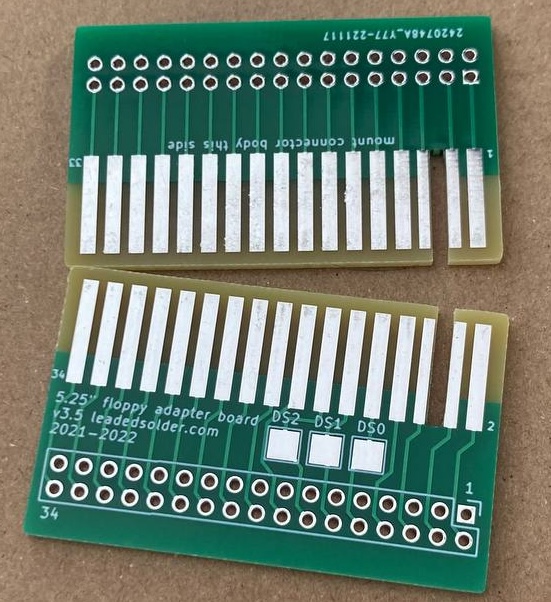
For long-term reliability, especially in humid environments or when the adapter is expected to be plugged and unplugged often, it's recommended that you pay extra at fabrication time to get hard gold fingers and a bevel. You can bevel it yourself with sandpaper, if needed.
This project was developed as part of a leaded solder repair of a Sharp X1turbo, and based on an older board developed for a conversion of a NEC PC-8801mkII.
Move the silkscreen for the female floppy-drive connector to match the label on the bottom of the board. The label was being ignored by assembly houses and this should help correct this behaviour.
Add "drive select" breakout pins on the top. This was done to enable a single HxC to emulate two drives on the NEC PC-8801. Thanks to Frio for requesting and co-operating with the development of this version of the adapter.
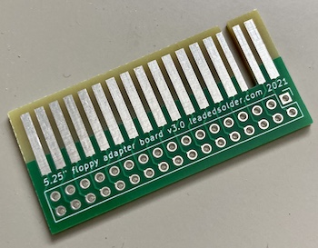
Original release of this board, fixing mounting issues from previous releases.
You can get the gerber files from the releases page. My usual fabs are JLCPCB, PCBWay and Osh Park.
You can also order it directly from the project page on PCBWay, which gives me some PCBWay credit that I can use on future custom board projects.
Note: this only works on the "v3.5" adapter with drive select pads on the top of it.
A single HxC floppy emulator can emulate two floppy drives at once. This usually "just works," but on the PC-8801 you must wire it a special way using two adapters.
The PC-88 has two separate floppy cables instead of one "bussed" cable. Although most signals are bussed together to the floppy drive, each cable has its own independent drive select signal. Both of those selects are on drive select 0 (DS0) which means that we must put a partially-populated adapter into one of the drives in order to provide "its" DS0 to the HxC as drive select 1 (DS1.)
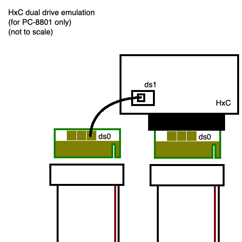
For more guidance, please consult the HxC forum thread for running two drives on a PC-8801.
| Qty | Value | Footprint | References |
|---|---|---|---|
| 3 | TestPoint | TestPoint:TestPoint_Pad_3.0x3.0mm | TP10, TP12, TP14 |
| 1 | Edge Connector | EdgeConnectors:FloppyEdge | J2 |
| 1 | Female Floppy Connector | EdgeConnectors:Floppy_Connector | J1 |

joypad-ai/joypad-os
Universal controller firmware for building adapters, dongles, and custom controllers.

OLIMEX/OLINUXINO
OLINUXINO is Open Source / Open Hardware, low cost from EUR 24 Linux Industrial grade Single Board Computer capable to operate -25+85C

jamro/tiny-engineer
A small desktop robot that brings an AI coding assistant to life, physically acting out when it reads files, thinks, writes code, and finishes work.

hackclub/OnBoard
💡 Join 1,000 teenagers and make your first PCB with a $100 grant!


Luos-io/luos_engine
Open-source and real-time orchestrator for cyber-physical-systems, to easily design, test and deploy embedded applications and digital twins.
It measures 45.7 × 26.1 mm and has 2 copper layers, 1.6 mm thick.
5 parts. The full list of its parts is on this page, with links to each part's symbol and footprint where PCBKit's library has them.
From the barbeque/floppy-edge-connector-adapter repository on GitHub, at the commit this page was made from: the board is floppy-adapter-2.kicad_pcb and its schematic floppy-adapter-2.kicad_sch. PCBKit opens the board in the browser, with nothing to install.
Its repository publishes it under the GPL-3.0 licence: you may reuse it on that licence's terms (keep the author's notice, and for a copyleft licence share your changes alike).