2 layers66.9 × 74.5 mm
 baldengineer/PCB-Routing-Speed-Run-Challenges3
How fast can you route a PCB in KiCad?
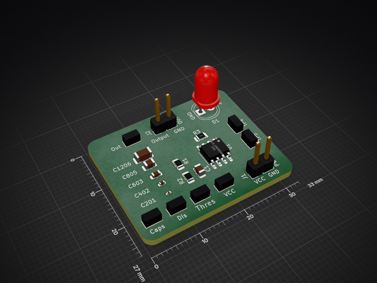
555 Multi Cap Board is an open-source printed circuit board by baldengineer, from the baldengineer/PCB-Routing-Speed-Run-Challenges repository on GitHub, published under the MIT licence. It is a 2-layer board of 33 × 27 mm with 20 parts on 8 nets.
Its parts include 6 capacitors, 3 resistors, 2 connectors, 1 IC and 1 diode.
How fast can you route a PCB in KiCad?
The PCB routing speed run is a self-moderated contest to see how fast you can route a PCB in KiCad.
The first circuit is a 555-timer board with multiple capacitor footprints. (Eventually, this could turn into a soldering challenge.)
.kicad_pcb or kicad_pcb-bak file until the timer starts.Time is counted from when the LiveSplit global hotkey is pressed until it is pressed again.
To accommodate computers of various speeds, DRC can be run AFTER the timer has stopped. However, if the board does not pass or there are unconnected nets, the run is disqualified.
Zone fills are not required during the run. (Default files have zones hidden.) You may let DRC fill them. This approach means the "unrouted" indicator may be more than zero when the timer is stopped. However, if the board does not pass DRC or there are unconnected nets, the run is disqualified.
When running DRC, these boxes should be checked:
kicad_pcb-bak file?It is a duplicate of the .kicad_pcb file, so you can just use "Revert to last backup" before starting a new run.
These files were created with KiCad 5.1.6.
Not sure if or how the KiCad version matters, but results should report the version as shown in the About box in PCBnew.
Install KiCad. Download this repository and open the .kicad_pcb file. Ideally, you'll also want to get LiveSplit. LiveSplit is an on-screen timer used by speedrunners for a first-order time result and lets viewers see what is happening.
And then practice. :)
Configuration files for LiveSplit will be uploaded soon to match @baldengineer's setup. Like video game speedrunning, the final results need to come from a video recording. Until then, let's just do pull-requests and add your times to the file "results.csv." Please, submit an issue or PR if you have a better idea.
Create a pull-request with modifications to the "results.csv" file. Results without video proof will be not be merged.
Ehhh, for now, no. But I do want to track results of live vs. not-live, at least for now.
Oops! Looks like you thought this one YouTube and not GitHub.
Watch James do his routing speed runs on Twitch: https://twitch.tv/baldengineer
| Qty | Value | Footprint | References |
|---|---|---|---|
| 2 | R_Small | Resistor_SMD:R_0805_2012Metric | R1, R2 |
| 2 | TestGND | My Libraries:Harwin-S1751-46-Test Point | TP4, TP5 |
| 1 | 10nF | Capacitor_SMD:C_0805_2012Metric | C1 |
| 1 | 330 | Resistor_SMD:R_0805_2012Metric | R3 |
| 1 | C_Small | Capacitor_SMD:C_0402_1005Metric | C402 |
| 1 | C_Small | Capacitor_SMD:C_1206_3216Metric | C1206 |
| 1 | C_Small | Capacitor_SMD:C_0603_1608Metric | C603 |
| 1 | C_Small | Capacitor_SMD:C_0201_0603Metric | C201 |
| 1 | C_Small | Capacitor_SMD:C_0805_2012Metric | C805 |
| 1 | Caps | My Libraries:Harwin-S1751-46-Test Point | TP3 |
| 1 | Dis | My Libraries:Harwin-S1751-46-Test Point | TP2 |
| 1 | LED_Small | LED_THT:LED_D5.0mm | D1 |
| 1 | OUT | Connector_PinHeader_2.54mm:PinHeader_1x02_P2.54mm_Vertical | J2 |
| 1 | Out | My Libraries:Harwin-S1751-46-Test Point | TP1 |
| 1 | PWR | Connector_PinHeader_2.54mm:PinHeader_1x02_P2.54mm_Vertical | J1 |
| 1 | Thres | My Libraries:Harwin-S1751-46-Test Point | TP7 |
| 1 | VCC | My Libraries:Harwin-S1751-46-Test Point | TP6 |
| 1 | bald_LM555xM | Package_SO:SOIC-8_3.9x4.9mm_P1.27mm | U1 |


atopile/atopile
Design circuit boards with code! ✨ Get software-like design reuse 🚀, validation, version control and collaboration in hardware; starting with electronics ⚡️

davidphilipbarr/Sweep
Sweep - a small promicro based keyboard inspired by the Ferris.

rusefi/rusefi
rusefi - GPL internal combustion engine control unit

hoglet67/RGBtoHDMI
Bare-metal Raspberry Pi project that provides pixel-perfect sampling of Retro Computer RGB/YUV video and conversion to HDMI

hackclub/OnBoard
💡 Join 1,000 teenagers and make your first PCB with a $100 grant!

FreeYourStream/freedeck-hardware
all the stuff you need to build your own FreeDeck
It measures 33 × 27 mm and has 2 copper layers, 1.6 mm thick.
20 parts. The full list of its parts is on this page, with links to each part's symbol and footprint where PCBKit's library has them.
From the baldengineer/PCB-Routing-Speed-Run-Challenges repository on GitHub, at the commit this page was made from: the board is 555 Multi-Cap Board/555 Multi-Cap Board.kicad_pcb. PCBKit opens the board in the browser, with nothing to install.
Its repository publishes it under the MIT licence: you may reuse it on that licence's terms (keep the author's notice, and for a copyleft licence share your changes alike).