

2 layers58.4 × 109.2 mm
Calibration PCB-2
badnat/NuDotCalibrationSystem
This project is for the NuDot Experiment https://jgruszko.web.unc.edu/experiments/. I am a student at UNC who will be graduating in May 2022. I am working with Dr.
9 parts
 badnat/NuDotCalibrationSystem
This project is for the NuDot Experiment https://jgruszko.web.unc.edu/experiments/. I am a student at UNC who will be graduating in May 2022. I am working with Dr.
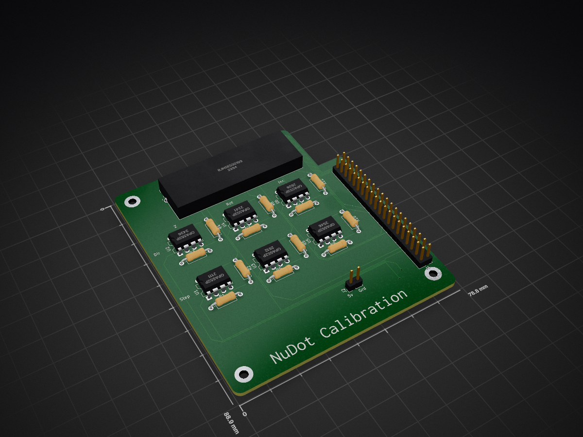
Calibration PCB-1 is an open-source printed circuit board by badnat, from the badnat/NuDotCalibrationSystem repository on GitHub. It is a 2-layer board of 78.7 × 88.9 mm with 24 parts on 88 nets, routed with 223 tracks and 2 vias.
It is built around the OPA552PA and RJHSE538103. Its parts include 12 resistors, 7 ICs and 2 connectors.
This project is for the NuDot Experiment https://jgruszko.web.unc.edu/experiments/. I am a student at UNC who will be graduating in May 2022. I am working with Dr. Gruszko to develop the code and electronics to control the calibration system for the NuDot experiment. The goal of this experiment is to detect neutrinoless double beta decay. Neutrinoless double beta decay is a very rare phenomenon. Because of this, it is difficult to distinguish signal from background during detection. NuDots goal is to reduce the background by detecting cherenkov radiation from single electron events produced by background events as opposed to the double electrons given off by double beta decay.
The goal of my code and electronics is to move a point beta ray source to an exact height, inclination, and rotation. Knowing these allows NuDot to calibrate the precise timings given by the detectors. These timings are extremely important for event building, where we determine details about the event causing the signal such as the position and energy.
Having previously taken a class full dedicated to working with microcontrollers, my first thought for this project was to use a Raspberry Pi. I ruled out Arduinos because I needed a file system to save multiple files and wanted the flexibility of a microcontroller with an OS for testing purposes. The problem ultimately boils down to moving 3 stepper motors into position, verifying the accuracy of that position, and recording that position for and future movements of the stepper.
I achieved these objectives by using python code to control the stepper motors and a c++ program to read the data from the stepper encoders, interpret the data, and store the position in a file. The python code will only move the stepper and the c++ code will only determine its position. This allows me to independently verify the positions of the steppers and compensate for any step skipping that might occur. This ensures that we always accurately know the positions of the steppers which is important for both calibration and mechanical reasons. Obviously we need to accurately know the position of the beta source to calibrate the system, but there are also a few mechanical hard stops that the steppers would be unable to push past (blocked by a lot of metal). I could have used a sensor to determine the position in space but decided to make my code very robust to avoid the issue all together.
I decided on an object oriented approach for ease of use and abstraction. The Calibrator object is primarily for abstraction and handling error handling/edge cases. It holds all of the Stepper objects which send the signals to the stepper motors to move them. The Stepper objects also use bash commands to start up the encoder code for that stepper motor.

| Qty | Value | Footprint | References |
|---|---|---|---|
| 12 | R | Resistor_THT:R_Axial_DIN0207_L6.3mm_D2.5mm_P10.16mm_Horizontal | R1, R2, R3, R4, R5, R6, R7, R8, R9, R10, R11, R12 |
| 6 | OPA552P | Package_DIP:DIP-8_W7.62mm | U1, U2, U3, U4, U5, U6 |
| 1 | RJHSE538103 | footprints:RJHSE538103 | U7 |
| 1 | Raspberry_Pi_2_3 | Connector_PinHeader_2.54mm:PinHeader_2x20_P2.54mm_Vertical | J1 |
| 1 | Screw_Terminal_01x02 | Connector_PinHeader_2.54mm:PinHeader_1x02_P2.54mm_Vertical | J2 |
The 21 most common of 24 parts.
badnat/NuDotCalibrationSystem
This project is for the NuDot Experiment https://jgruszko.web.unc.edu/experiments/. I am a student at UNC who will be graduating in May 2022. I am working with Dr.


dotnet/iot
This repo includes .NET Core implementations for various IoT boards, chips, displays and PCBs.

pascallanger/DIY-Multiprotocol-TX-Module
Multiprotocol TX Module (or MULTI-Module) is a 2.4GHz transmitter module which controls many different receivers and models.


rusefi/rusefi
rusefi - GPL internal combustion engine control unit

DraftShift/StealthChanger
Tool changing system for Vorons and other front mount printer motion systems, not just stealthburner.

VoronDesign/Voron-Hardware
Cool Hardware designed by the Voron Design group

hackclub/OnBoard
💡 Join 1,000 teenagers and make your first PCB with a $100 grant!
It measures 78.7 × 88.9 mm and has 2 copper layers, 1.6 mm thick.
24 parts, built around the OPA552PA and RJHSE538103. The full list of its parts is on this page, with links to each part's symbol and footprint where PCBKit's library has them.
From the badnat/NuDotCalibrationSystem repository on GitHub, at the commit this page was made from: the board is kiCadFiles/Calibration-PCB-1.kicad_pcb and its schematic kiCadFiles/Calibration-PCB-1.kicad_sch. PCBKit opens the board in the browser, with nothing to install.
Its repository states no licence, so its author keeps all rights: ask badnat before reusing the design.