2 layers69 × 43 mm
Diagral uart esp32
nicolas5000/diagral-esp32
This project permits to connect Home Assitant to your Diagral alarm system DIAG91AGFK (using the 20 pins connector on the back)
12 parts6Apache-2.0

 bablokb/pcb-datalogger-v4e
Pico Board for Data-Logging (Ethernet Version)
Pico datalogger v4e is an open-source printed circuit board by bablokb, from the bablokb/pcb-datalogger-v4e repository on GitHub, published under the CC-BY-SA-4.0 licence. It is a 2-layer board of 59.1 × 75.2 mm with 27 parts on 43 nets, routed with 167 tracks and 29 vias.
It is built around the WIZ850IO and RFM95W-868S2. Its parts include 8 connectors, 5 resistors, 4 switches, 1 capacitor and 1 IC. It belongs with the sensors and measurement boards and the RP2040 boards of this library.


Here are the KiCAD (v7) design-files for the Datalogger-V4e-PCB.
This is a simplified datalogger-board with the option to connect a Wiznet W5500 breakout board for Ethernet connectivity. This version neither has any power-management circuitry nor does it include a XTSD-chip for storage. A WLAN-version V4w is planned with a similar form-factor and power-management included. Storage is not included since Pico2 (and clones) now have enough internal flash for an embedded "/saves"-partition.
The PCB supports an adapter connected with normal DuPont-sockets and a RTC breakout. It is also possible to attach one of these cheap standard 128x64 mini OLED displays.
The current configuration in production_files only includes the
small resistors and capacitors. The buttons, the LoRa-chip and antenna
connectors have to be hand-soldered like all the socket/pin
connectors. If you prefer SMT-assembly, you have to change the
respective properties of the components within KiCAD and regenerate
BOM and CPL files.
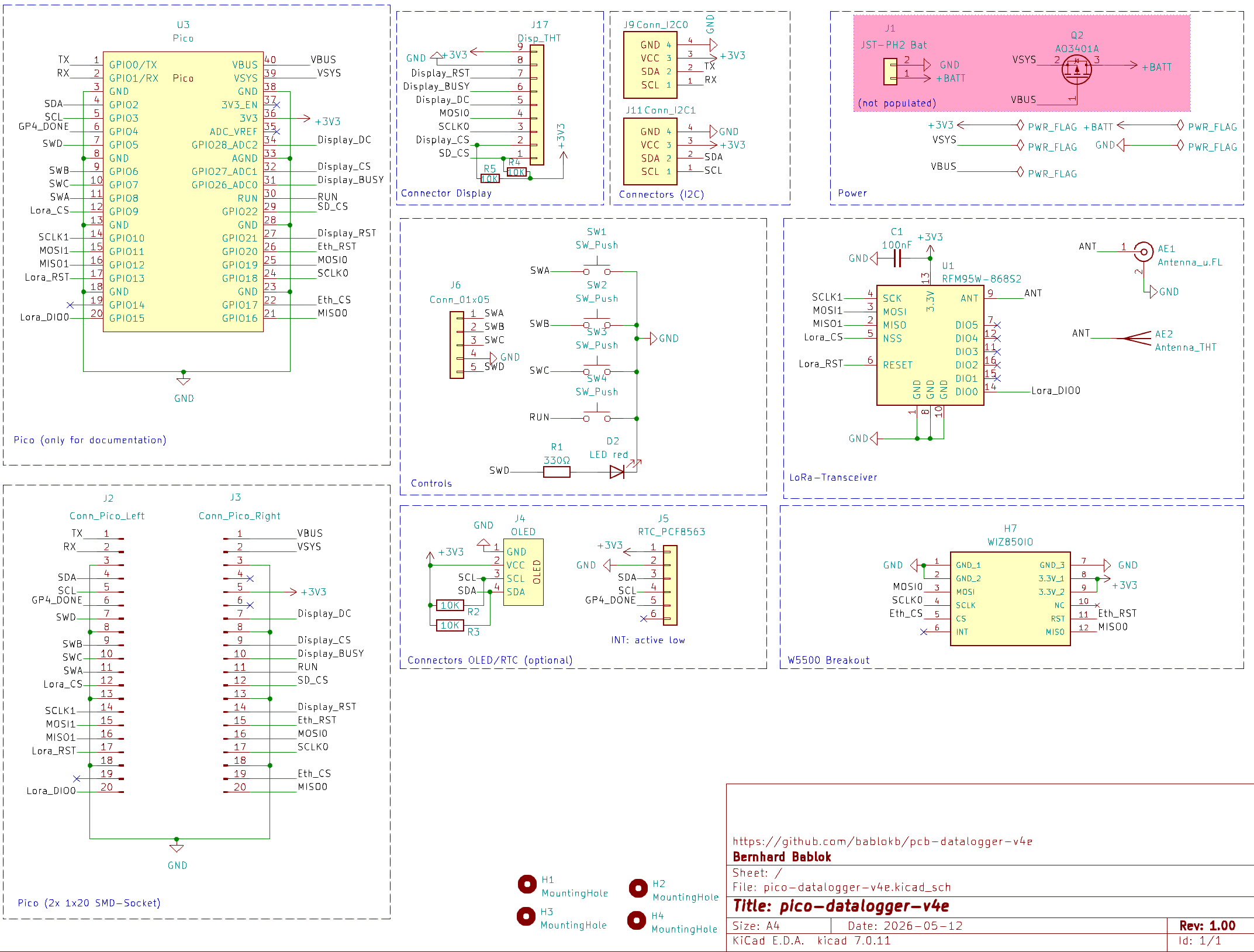
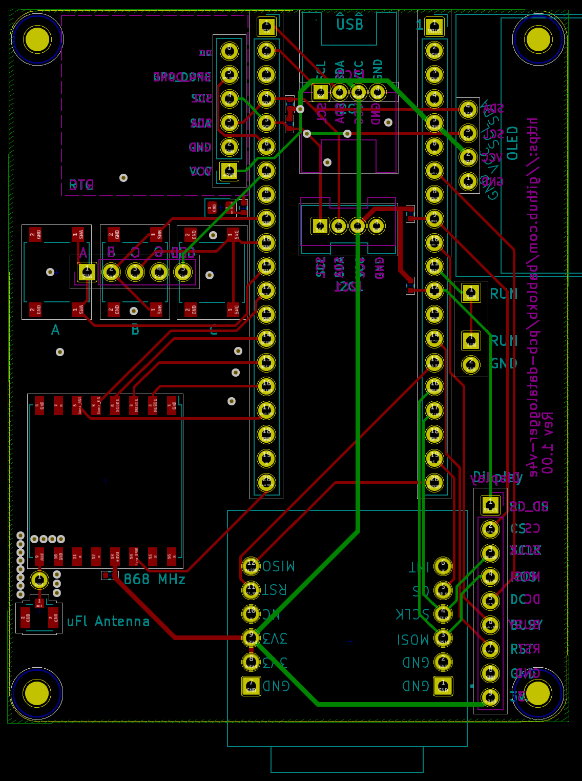
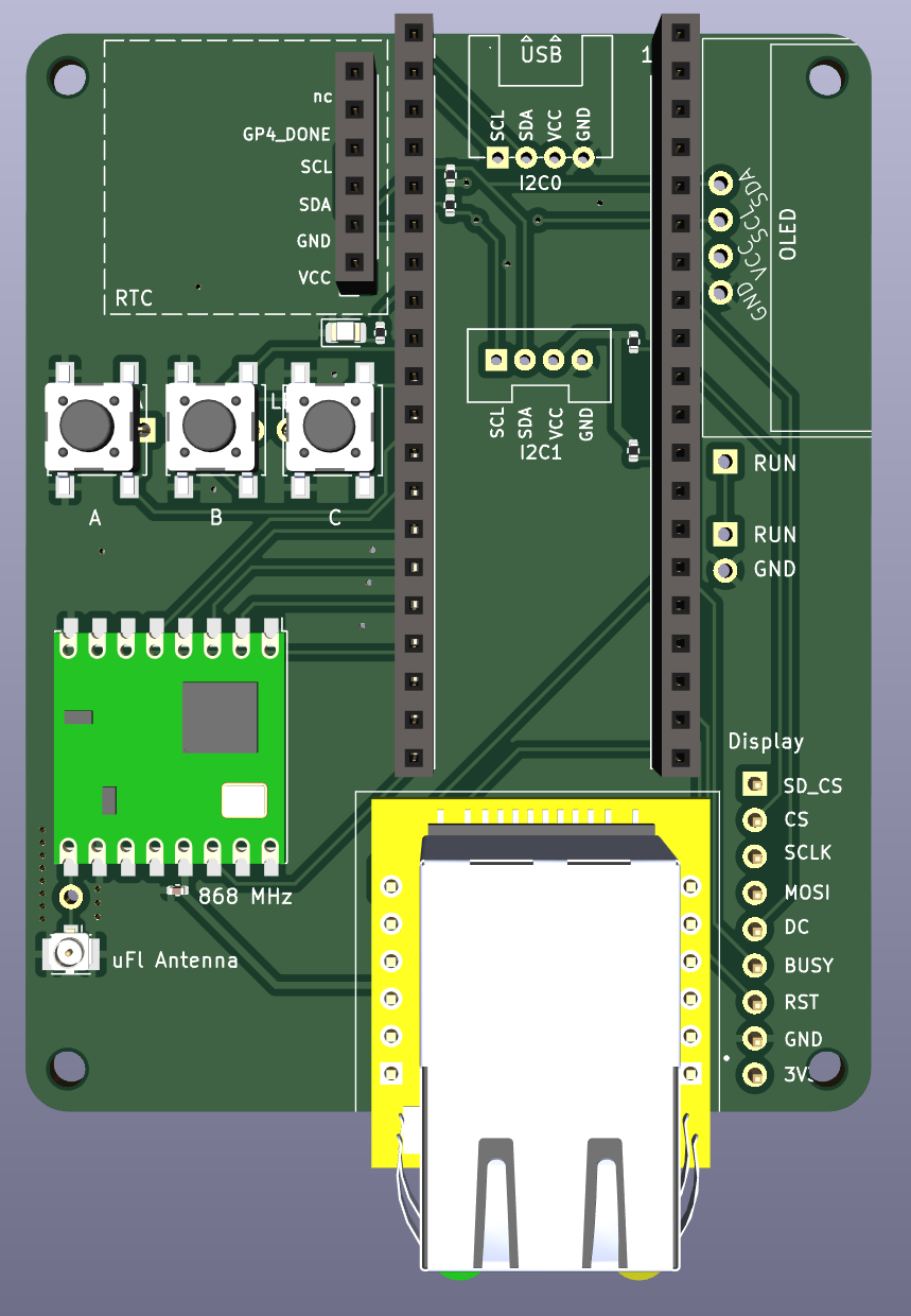
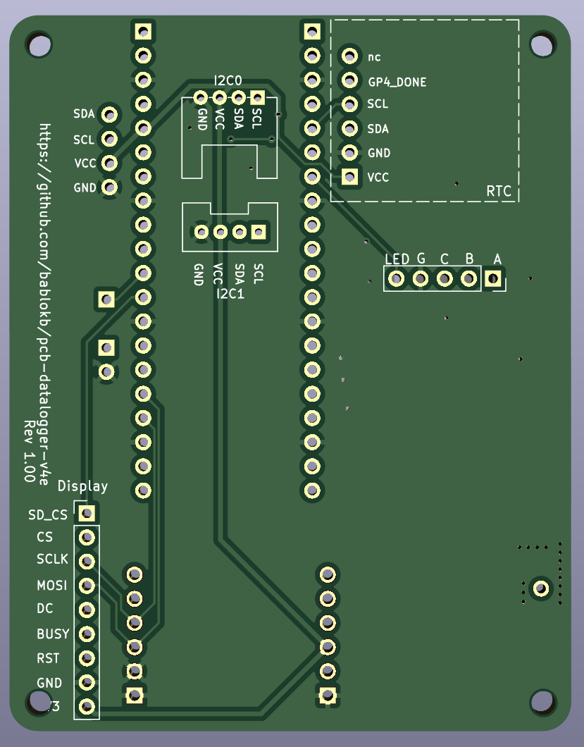

This work is licensed under a Creative Commons Attribution-ShareAlike 4.0 International License.

| Qty | Value | Footprint | References |
|---|---|---|---|
| 4 | 10K | Resistor_SMD:R_0402_1005Metric | R2, R3, R4, R5 |
| 4 | MountingHole | MountingHole:MountingHole_2.5mm | H1, H2, H3, H4 |
| 3 | SW_Push | user:SW_SPST_B3S-1000 | SW1, SW2, SW3 |
| 1 | 100nF | Capacitor_SMD:C_0402_1005Metric | C1 |
| 1 | 330Ω | Resistor_SMD:R_0402_1005Metric | R1 |
| 1 | Antenna_THT | user:Antenna_THT | AE2 |
| 1 | Antenna_u.FL | user:U.FL_Hirose_U.FL-R-SMT-1_Vertical | AE1 |
| 1 | Conn_01x05 | Connector_PinSocket_2.54mm:PinSocket_1x05_P2.54mm_Vertical | J6 |
| 1 | Conn_I2C0 | user:grove_horizontal | J9 |
| 1 | Conn_I2C1 | user:grove_vertical | J11 |
| 1 | Conn_Pico_Left | Connector_PinSocket_2.54mm:PinSocket_1x20_P2.54mm_Vertical | J2 |
| 1 | Conn_Pico_Right | Connector_PinSocket_2.54mm:PinSocket_1x20_P2.54mm_Vertical | J3 |
| 1 | Disp_THT | Connector_PinHeader_2.54mm:PinHeader_1x09_P2.54mm_Vertical | J17 |
| 1 | LED red | LED_SMD:LED_0805_2012Metric | D2 |
| 1 | OLED | user:OLED_Display | J4 |
| 1 | RFM95W-868S2 | user:HOPERF_RFM9XW_SMD | U1 |
| 1 | RTC_PCF8563 | Connector_PinSocket_2.54mm:PinSocket_1x06_P2.54mm_Vertical | J5 |
| 1 | SW_Push | user:SW_PUSH_SLIM_1x4 | SW4 |
| 1 | WIZ850IO | user:WIZ850IO | H7 |
nicolas5000/diagral-esp32
This project permits to connect Home Assitant to your Diagral alarm system DIAG91AGFK (using the 20 pins connector on the back)


kellerkindt/bluepill_sensor
Bluepill stm31f103 ethernet sensor extension board with SW written in Rust


flintwinters/helix-hardware
KiCad 10 schematic for a USB powered STM32C071FBP6 with one shared SPI bus. The WIZ850io W5500 module and a 3.3 V, six wire microSD SPI breakout have separate chip selects. SWD is available for first firmware bring-up.

JoachimBose/nabby-linux
An Allwinner F1C100s / F1C200s buildroot external tree for (among others) the hardware challenge for VUCTF-2026


It measures 59.1 × 75.2 mm and has 2 copper layers, 1.6 mm thick.
27 parts, built around the WIZ850IO and RFM95W-868S2. The full list of its parts is on this page, with links to each part's symbol and footprint where PCBKit's library has them.
From the bablokb/pcb-datalogger-v4e repository on GitHub, at the commit this page was made from: the board is pico-datalogger-v4e.kicad_pcb and its schematic pico-datalogger-v4e.kicad_sch. PCBKit opens the board in the browser, with nothing to install.
Its repository publishes it under the CC-BY-SA-4.0 licence: you may reuse it on that licence's terms (keep the author's notice, and for a copyleft licence share your changes alike).