2 layers91.4 × 50.8 mm

 bablokb/pcb-datalogger-sensor-pcb
Sensor PCB for the Pico Datalogger-v2
Pico sensor pcb is an open-source printed circuit board by bablokb, from the bablokb/pcb-datalogger-sensor-pcb repository on GitHub, published under the CC-BY-SA-4.0 licence. It is a 2-layer board of 56 × 70 mm with 39 parts on 30 nets, routed with 192 tracks and 34 vias.
It is built around the AHT20, BH1750FVI-TR and MP34DT05TR-A. Its parts include 8 resistors, 6 capacitors, 6 connectors, 5 switches and 4 ICs. It belongs with the sensors and measurement boards and the RP2040 boards of this library.


Here are the KiCAD (v6) design-files for the sensor-pcb, a complementary pcb for the datalogger-v2 pcb.
Target components:
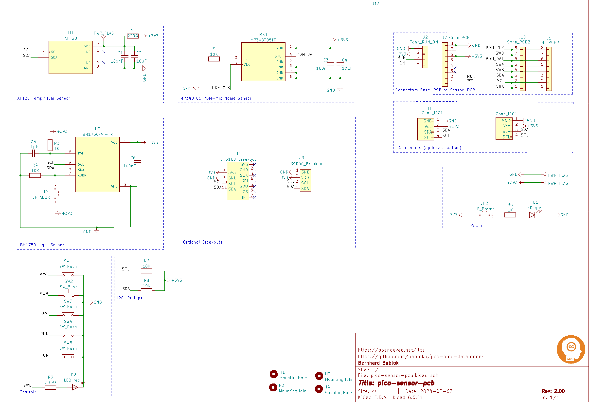
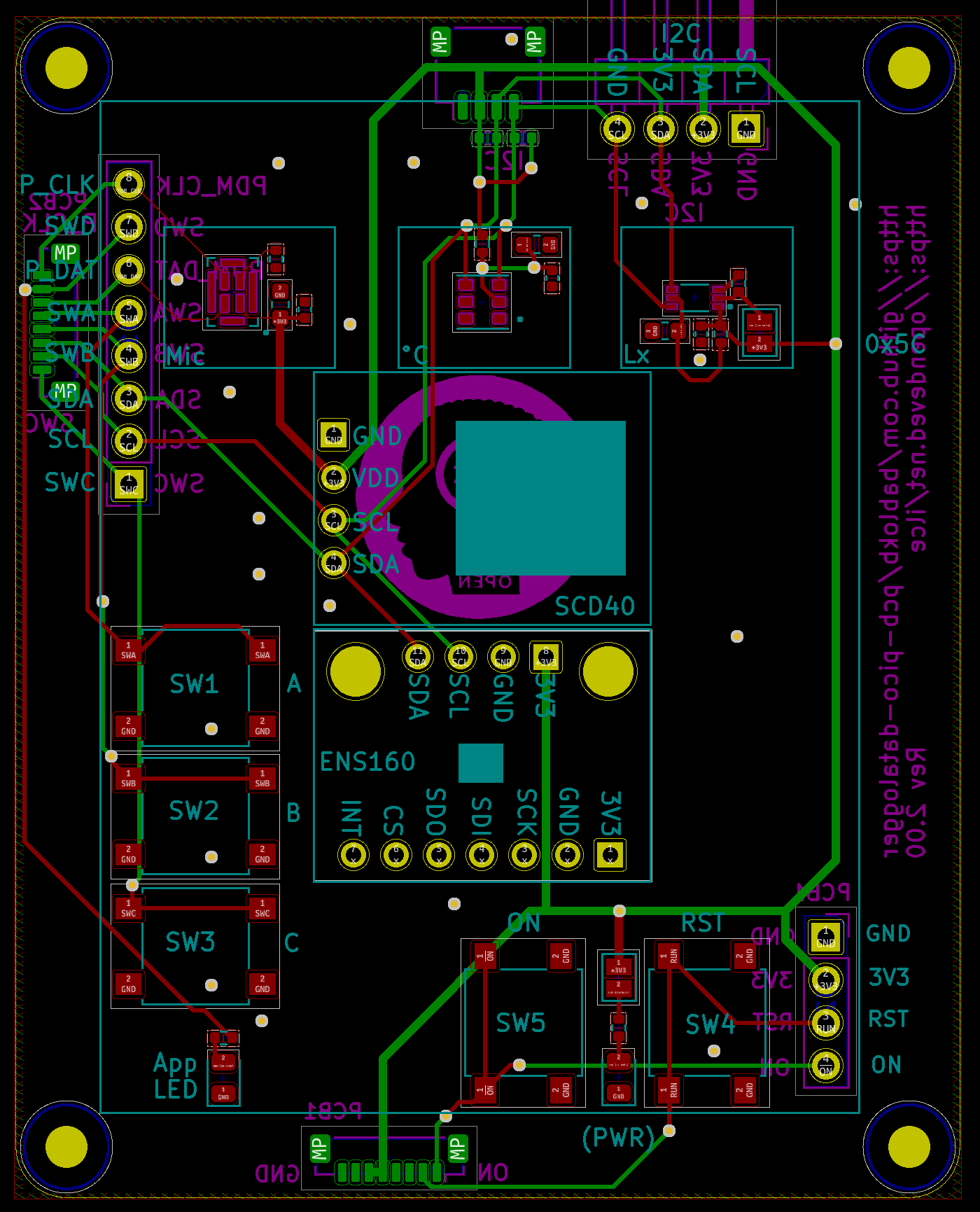
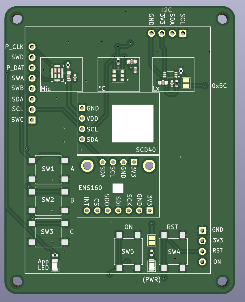
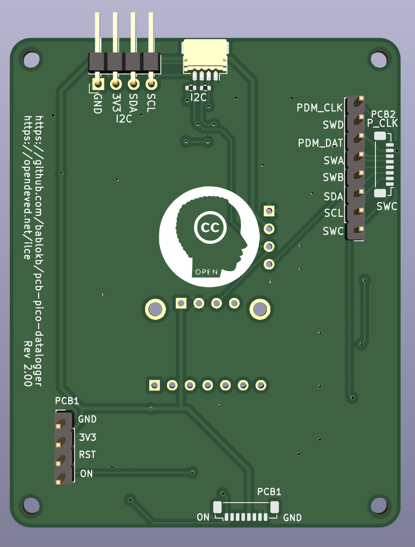

This work is licensed under a Creative Commons Attribution-ShareAlike 4.0 International License.

| Qty | Value | Footprint | References |
|---|---|---|---|
| 5 | SW_Push | Button_Switch_SMD:SW_SPST_B3S-1000 | SW1, SW2, SW3, SW4, SW5 |
| 4 | 10K | Resistor_SMD:R_0402_1005Metric | R2, R4, R7, R8 |
| 4 | MountingHole | MountingHole:MountingHole_2.5mm | H1, H2, H3, H4 |
| 3 | 100nF | Capacitor_SMD:C_0402_1005Metric | C1, C3, C6 |
| 2 | 10µF | Capacitor_SMD:C_0603_1608Metric | C2, C4 |
| 2 | 1K | Resistor_SMD:R_0402_1005Metric | R3, R5 |
| 1 | 1µF | Capacitor_SMD:C_0603_1608Metric | C5 |
| 1 | 220Ω | Resistor_SMD:R_0402_1005Metric | R1 |
| 1 | 330Ω | Resistor_SMD:R_0402_1005Metric | R6 |
| 1 | AHT20 | user:AHT20 | U1 |
| 1 | BH1750FVI-TR | user:BH1750 | U2 |
| 1 | Conn_I2C1 | Connector_JST:JST_SH_SM04B-SRSS-TB_1x04-1MP_P1.00mm_Horizontal | J11 |
| 1 | Conn_I2C1 | Connector_PinHeader_2.54mm:PinHeader_1x04_P2.54mm_Horizontal | J13 |
| 1 | Conn_PCB2 | Connector_JST:JST_SUR_BM08B-SURS-TF_1x08-1MP_P0.80mm_Vertical | J10 |
| 1 | Conn_PCB_1 | Connector_JST:JST_SUR_BM08B-SURS-TF_1x08-1MP_P0.80mm_Vertical | J7 |
| 1 | Conn_RUN_ON | Connector_PinHeader_2.54mm:PinHeader_1x04_P2.54mm_Vertical | J2 |
| 1 | ENS160_Breakout | user:ENS160_Breakout | U4 |
| 1 | JP_ADDR | Jumper:SolderJumper-2_P1.3mm_Open_Pad1.0x1.5mm | JP1 |
| 1 | JP_Power | Jumper:SolderJumper-2_P1.3mm_Open_Pad1.0x1.5mm | JP2 |
| 1 | LED green | LED_SMD:LED_0805_2012Metric | D1 |
| 1 | LED red | LED_SMD:LED_0805_2012Metric | D2 |
| 1 | LOGO | LOGO | G*** |
| 1 | MP34DT05TR | user:MP34DT05TR | MK1 |
| 1 | SCD40_Breakout | user:SCD40_Breakout | U3 |
| 1 | THT_PCB2 | Connector_PinHeader_2.54mm:PinHeader_1x08_P2.54mm_Vertical | J1 |
It measures 56 × 70 mm and has 2 copper layers, 1.6 mm thick.
39 parts, built around the AHT20, BH1750FVI-TR and MP34DT05TR-A. The full list of its parts is on this page, with links to each part's symbol and footprint where PCBKit's library has them.
From the bablokb/pcb-datalogger-sensor-pcb repository on GitHub, at the commit this page was made from: the board is pico-sensor-pcb.kicad_pcb and its schematic pico-sensor-pcb.kicad_sch. PCBKit opens the board in the browser, with nothing to install.
Its repository publishes it under the CC-BY-SA-4.0 licence: you may reuse it on that licence's terms (keep the author's notice, and for a copyleft licence share your changes alike).


conol-ai/openwalkietalkie
OpenMicroDial firmware — Rust/embassy on SiFli SF32LB52 (LilyGo T-Display SF32 dev board)

janekc/led-tube
It should run with 4 x 18650 lithium battery cells, that can be recharged through USB Power Delivery 3.0 with up to 18W.

joshitha-c/microphone
A compact USB digital microphone development board built around the Raspberry Pi RP2040 microcontroller and the STMicroelectronics MP34DT05TR-A digital MEMS microphone.

okrastew-2/ce346-spring-2026
Firmware and PCB design for COMP_ENG 346: Microcontroller System Design.

Rujul-Rumale/SpecVue
4-layer ESP32-S3 smart-glasses PCB with camera live streaming and on-device object classification over Wi-Fi.

RV-crtl/Digital-Hearing-Aid-G1
Anna — controls · Ryan — BT/telecoil · Mariya — microphone/DSP · Naomi — speaker output · Interface contracts