
2 layers68.8 × 53.6 mm
ZArduino
zmaker/arduino_cookbook
gli sketch del nuovo progetto Arduino Cookbook e dei video di YouTube
46 parts269
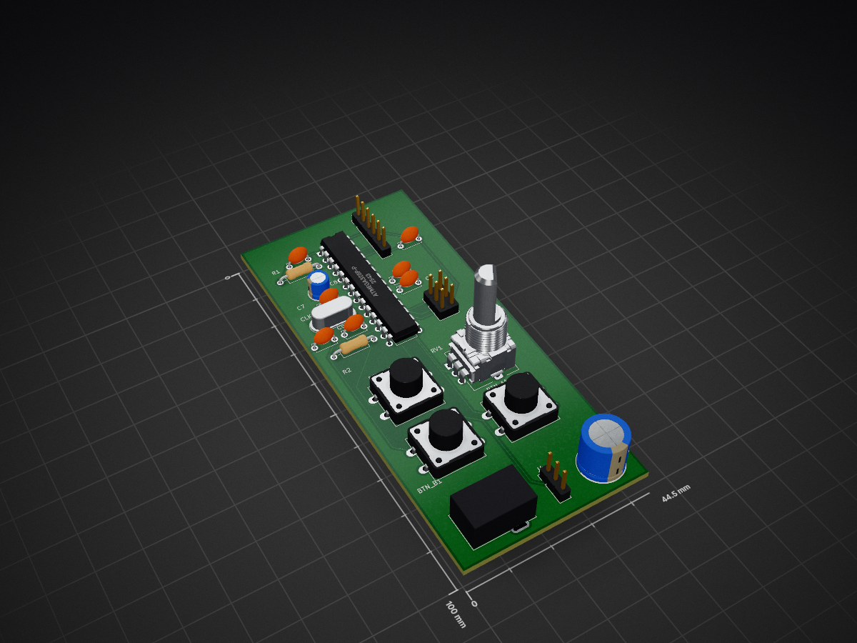
 audy910/LED-PCB-Controller
A custom ATmega328P controller board for WS2812B addressable LED strips, designed in KiCad and built for a light box.
LightBoxPCB is an open-source printed circuit board by audy910, from the audy910/LED-PCB-Controller repository on GitHub. It is a 2-layer board of 44.5 × 100 mm with 21 parts on 29 nets, routed with 84 tracks and 0 vias.
It is built around the ATMEGA328P-PU. Its parts include 9 capacitors, 4 connectors, 2 resistors and 1 IC. It belongs with the AVR (ATmega, ATtiny) boards of this library.
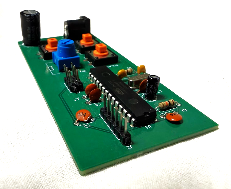
A custom ATmega328P controller board for WS2812B addressable LED strips, designed in KiCad and built for a light box. Three buttons and a brightness knob drive three lighting modes, from adjustable warm/cool white to six animated "party" effects, all running on a standalone Arduino-compatible board with no dev board required.
| File | Description |
|---|---|
Lights_For_lightbox.ino | Arduino firmware (FastLED) |
LightBoxPCB.kicad_sch | KiCad schematic |
LightBoxPCB.kicad_pcb | KiCad PCB layout (2-layer) |
Gerbers.zip | Fabrication-ready Gerber and drill files |
The KiCad files were saved with KiCad 10, so open them with KiCad 10 or newer.
The MODE button cycles through White → Party → Color. Buttons A and B change behavior depending on the active mode. The potentiometer sets brightness in every mode.
| Mode | Button A | Button B |
|---|---|---|
| WHITE | Warmer | Cooler |
| PARTY | Next effect preset | Shift color |
| COLOR | Toggle auto-cycle | Step hue |
| ATmega328P Pin | Arduino Pin | Function |
|---|---|---|
| PD6 (pin 12) | D6 | LED data out (through 470 Ω series resistor) |
| PC0 (pin 23) | A0 | Brightness potentiometer wiper |
| PD2 (pin 4) | D2 | MODE button (to GND, internal pull-up) |
| PD3 (pin 5) | D3 | Button A (to GND, internal pull-up) |
| PD4 (pin 6) | D4 | Button B (to GND, internal pull-up) |
| PD0 / PD1 | D0 / D1 | FTDI serial RX / TX |
| PB3 / PB4 / PB5 | D11 / D12 / D13 | ICSP MOSI / MISO / SCK |
| Ref | Type | Pinout |
|---|---|---|
| J3 | Barrel jack | 5 V power input |
| J4 | 1×3 header | LED strip: 5V, DATA, GND |
| J1 | 2×3 header | ICSP (standard AVR pinout) |
| J2 | 1×6 header | FTDI: GND, CTS (n/c), VCC, TX, RX, DTR |
| Ref | Value | Footprint |
|---|---|---|
| U1 | ATmega328P-P | DIP-28 |
| CLK1 | 16 MHz crystal | HC49-4H |
| C4, C5 | 22 pF | Ceramic disc, 5 mm pitch |
| C1, C2, C3, C6, C7 | 100 nF | Ceramic disc, 5 mm pitch |
| C8 | 10 µF | Radial electrolytic, 5 mm dia. |
| C9 | 1000 µF | Radial electrolytic, 10 mm dia. |
| R1 | 10 kΩ | Axial (reset pull-up) |
| R2 | 470 Ω | Axial (LED data series resistor) |
| RV1 | Potentiometer | Alps RK09L, vertical |
| BTN_MODE1, BTN_A1, BTN_B1 | Tactile switch | 12 mm THT |
| J1 | 2×3 pin header | 2.54 mm |
| J2 | 1×6 pin header | 2.54 mm |
| J3 | Barrel jack | Würth 6941xx301002 |
| J4 | 1×3 pin header | 2.54 mm |
The barrel jack feeds the 5 V rail directly. There's no on-board regulator, so use a regulated 5 V supply. Feeding it 9 V or 12 V will damage the MCU and the LEDs.
Each WS2812B can draw up to about 60 mA at full white. The default 11-LED configuration needs up to about 0.66 A, so a 5 V / 1 A supply is plenty. Scale the supply up if you increase NUM_LEDS.
Gerbers.zip directly to a PCB fab (JLCPCB, PCBWay, OSH Park, etc.). The defaults are fine: 2 layers, 1.6 mm, HASL.Edit these defines at the top of Lights_For_lightbox.ino to match your setup:
#define NUM_LEDS       11     // number of LEDs on your strip
#define COLOR_ORDER    GRB    // change if colors look swapped
#define DEBOUNCE_MS    600    // raise if buttons still double-trigger
#define CONFIRM_MS 12 // noise-rejection re-check delaySet the board to Arduino Uno (ATmega328P, 16 MHz). Then use one of these methods.
Option A: ICSP (blank chip)
Option B: FTDI (bootloader installed)
You can also flash the chip in an Arduino Uno and move it to the board.
| Symptom | Likely cause and fix |
|---|---|
| Buttons trigger on their own | EMI from the LED data line. Raise DEBOUNCE_MS (e.g. 800) and keep the LED cable away from the button wiring. |
| LEDs flicker or reset at high brightness | Supply can't keep up. Use a beefier 5 V supply and confirm C9 is installed. |
| Wrong colors (e.g. red shows as green) | Change COLOR_ORDER to RGB or BRG. |
| Upload fails over FTDI | Bootloader not installed (use Option A first), TX/RX swapped, or the adapter is set to 3.3 V. |
| Board doesn't run after burning bootloader | Check the crystal and its 22 pF load caps. |
Audrey — Computer Engineering, UC Riverside
| Qty | Value | Footprint | References |
|---|---|---|---|
| 5 | 100nF | Capacitor_THT:C_Disc_D5.0mm_W2.5mm_P5.00mm | C1, C2, C3, C6, C7 |
| 3 | SW_Push | Button_Switch_THT:SW_PUSH-12mm | BTN_A1, BTN_B1, BTN_MODE1 |
| 2 | 22pF | Capacitor_THT:C_Disc_D5.0mm_W2.5mm_P5.00mm | C4, C5 |
| 1 | 1000uF | Capacitor_THT:CP_Radial_D10.0mm_P5.00mm | C9 |
| 1 | 10k | Resistor_THT:R_Axial_DIN0207_L6.3mm_D2.5mm_P10.16mm_Horizontal | R1 |
| 1 | 10uF | Capacitor_THT:CP_Radial_D5.0mm_P2.50mm | C8 |
| 1 | 16MHz | Crystal:Crystal_HC49-4H_Vertical | CLK1 |
| 1 | 470 | Resistor_THT:R_Axial_DIN0207_L6.3mm_D2.5mm_P10.16mm_Horizontal | R2 |
| 1 | ATmega328P-P | Package_DIP:DIP-28_W7.62mm | U1 |
| 1 | Barrel_Jack | Connector_BarrelJack:BarrelJack_Wuerth_6941xx301002 | J3 |
| 1 | Conn_01x03 | Connector_PinHeader_2.54mm:PinHeader_1x03_P2.54mm_Vertical | J4 |
| 1 | Conn_01x06 | Connector_PinHeader_2.54mm:PinHeader_1x06_P2.54mm_Vertical | J2 |
| 1 | Conn_02x03_Odd_Even | Connector_PinHeader_2.54mm:PinHeader_2x03_P2.54mm_Vertical | J1 |
| 1 | R_Potentiometer | Potentiometer_THT:Potentiometer_Alps_RK09L_Single_Vertical | RV1 |
It measures 44.5 × 100 mm and has 2 copper layers, 1.6 mm thick.
21 parts, built around the ATMEGA328P-PU. The full list of its parts is on this page, with links to each part's symbol and footprint where PCBKit's library has them.
From the audy910/LED-PCB-Controller repository on GitHub, at the commit this page was made from: the board is LightBoxPCB.kicad_pcb and its schematic LightBoxPCB.kicad_sch. PCBKit opens the board in the browser, with nothing to install.
Its repository states no licence, so its author keeps all rights: ask audy910 before reusing the design.
zmaker/arduino_cookbook
gli sketch del nuovo progetto Arduino Cookbook e dei video di YouTube

coseyfannitutti/discipad
17-key numpad assembled with only through hole components, including usb type-c

matthewcieplak/super-sixteen
Code and schematics for the Super Sixteen Eurorack sequencer

coseyfannitutti/romeo
Staggered 40% keyboard pcb that can be assembled with only through hole components, including USB Type-C

mattybrad/drumkid
Version 4 was the first successful working design, with full code, schematics, Gerbers, etc available on GitHub.


leomil72/LM80C
A Z80-based homebrew computer withTMS9918, AY-3-8910, Z80 CTC, Z80 PIO, and Z80 SIO
