2 layers123 × 87.5 mm
FastLOGIC
Neumi/fastLOGIC
An affordable Arduino-based board designed for straightforward (industrial) logic control, ideal for building small-scale automation and control solutions.
180 parts23MIT

 Atomicbeast101/smart-doorbell
A KiCad-designed smart doorbell PCB that utilizes the existing doorbell transformer to power the board, the doorbell button wiring to detect actions, and controls the chime.
Doorbell with External ESP8266 is an open-source printed circuit board by Atomicbeast101, from the Atomicbeast101/smart-doorbell repository on GitHub, published under the MIT licence. It is a 4-layer board of 70 × 50 mm with 28 parts on 28 nets, routed with 92 tracks and 15 vias.
It is built around the WEMOS D1 MINI and EL817. Its parts include 7 resistors, 5 diodes, 5 connectors, 2 ICs and 1 transistor. It belongs with the home automation and IoT boards and the ESP8266 boards of this library.


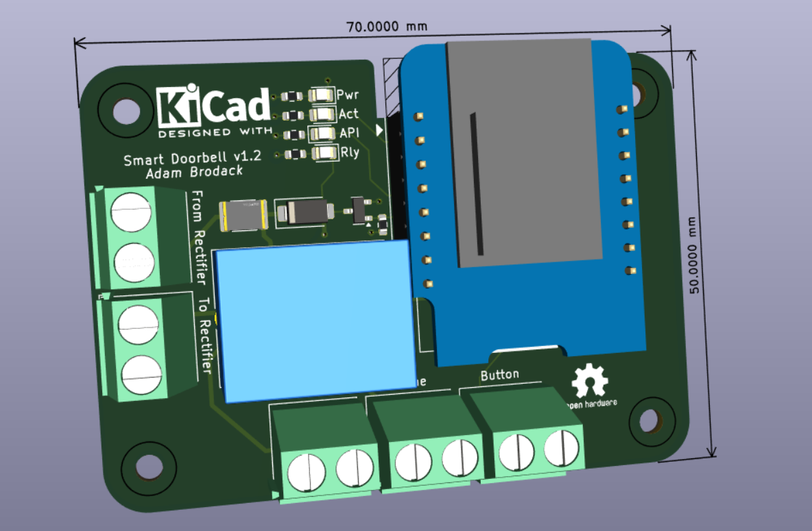
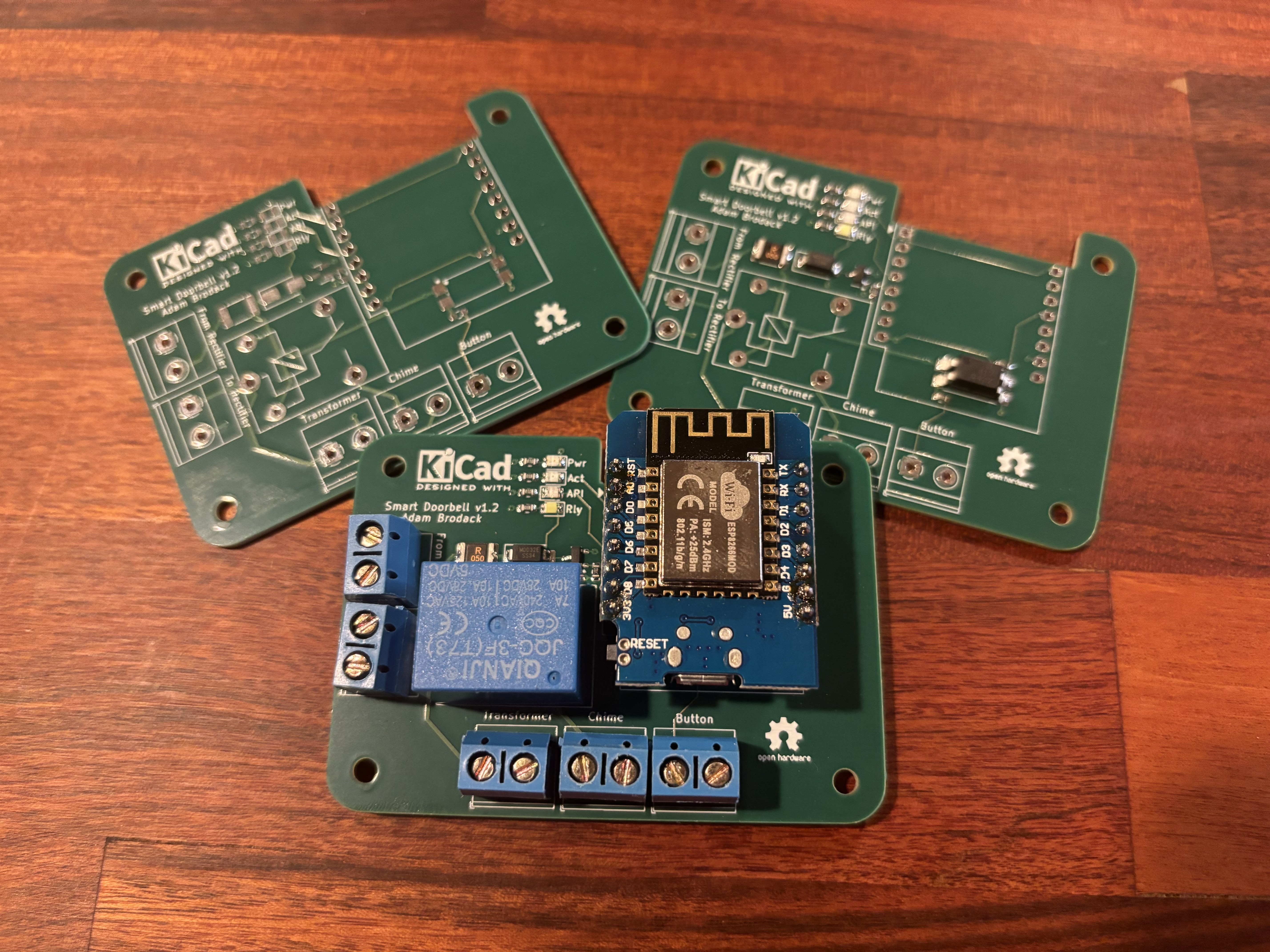
A KiCad-designed smart doorbell PCB that provides the capability to use the existing doorbell transformer to power the board (via a buck converter), utilize the existing doorbell button wiring, and control the doorbell chime. The idea is to leverage the existing equipment and make it smarter by enabling it to detect doorbell presses and send notifications to Home Assistant while still triggering the doorbell chime.
This design has gone through its second revision to achieve a working version. The third revision was done to improve the wiring layout, otherwise the schematic design is the same.
PCBWay reached out to me in October 2024 to sponsor the manufacturing of the v1.2 revision.
They have a pretty cool plugin for KiCad that generates the manufacturing files and sends them directly to PCBWay's ordering page. All I had to do was review the order options, modify any as needed, and add it to my cart. The main difference from JLCPCB is that I didn't have to identify the part numbers in the schematic file; they did it for me, which is nice.
However, it would be beneficial to have the option to specify which part numbers should be identified, so they would only need to reach out to me for confirmation on the quote rather than asking me for part numbers on the non-assembled parts.
After a few weeks, the PCBs were shipped to me. I am quite satisfied with their manufacturing quality. One nice feature is that they provide one PCB without any assembled parts, along with five that have the components soldered on. This could be useful for those who want to see how it looks without the parts in the way for troubleshooting purposes. I was able to get other parts soldered on without any issues.
You can check out their site for more details or to place an order: https://www.pcbway.com/.
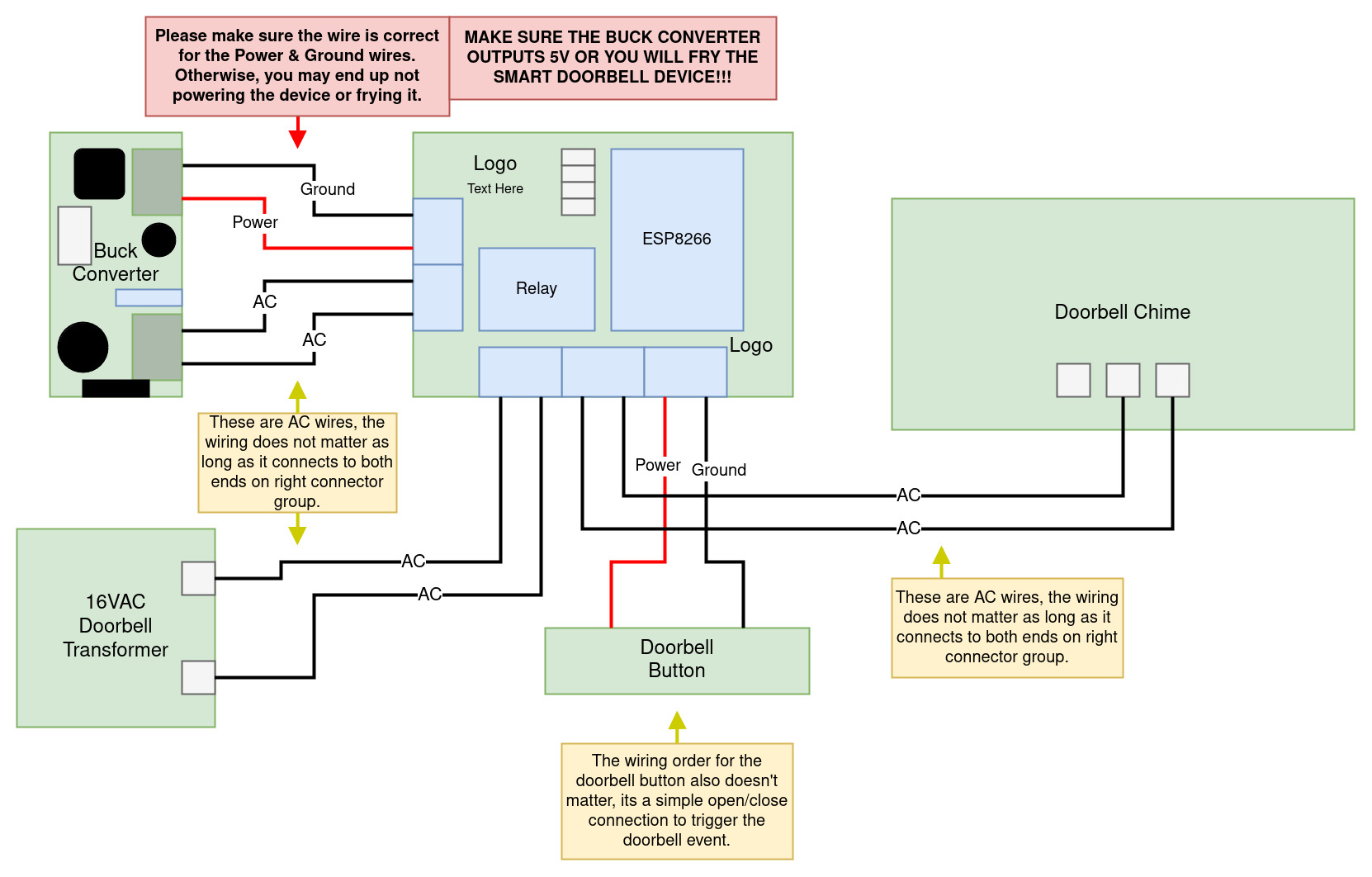
ESPHome/ folder (WIP as of 10/2/2024).Here's a diagram of how this smart doorbell interacts with a typical home's doorbell system with standard 16VAC transformer.
The designs can be seen using Kicanvas tool here (this tool is still in alpha stage as of September 2024).
| Qty | Value | Footprint | References |
|---|---|---|---|
| 5 | 1K | Resistor_SMD:R_0603_1608Metric | R101, R102, R103, R104, R106 |
| 4 | MountingHole | MountingHole:MountingHole_3mm | H101, H102, H103, H104 |
| 2 | 10K | Resistor_SMD:R_0603_1608Metric | R105, R107 |
| 1 | Button | TerminalBlock_Phoenix:TerminalBlock_Phoenix_MKDS-1,5-2_1x02_P5.00mm_Horizontal | J105 |
| 1 | Chime | TerminalBlock_Phoenix:TerminalBlock_Phoenix_MKDS-1,5-2_1x02_P5.00mm_Horizontal | J104 |
| 1 | D_Small | Diode_SMD:D_SMA | D105 |
| 1 | EL817 | footprints:EL817S1(C)(TU)-F | U103 |
| 1 | From Rectifier | TerminalBlock_Phoenix:TerminalBlock_Phoenix_MKDS-1,5-2_1x02_P5.00mm_Horizontal | J102 |
| 1 | Green | LED_SMD:LED_0805_2012Metric | D102 |
| 1 | Polyfuse_Small | footprints:Fuse_1812_4532Metric | F101 |
| 1 | Q_NMOS_GSD | Package_TO_SOT_SMD:SOT-23 | Q101 |
| 1 | Red | LED_SMD:LED_0805_2012Metric | D101 |
| 1 | Relay | Relay_THT:Relay_SPDT_SANYOU_SRD_Series_Form_C | K101 |
| 1 | To Rectifier | TerminalBlock_Phoenix:TerminalBlock_Phoenix_MKDS-1,5-2_1x02_P5.00mm_Horizontal | J103 |
| 1 | Transformer | TerminalBlock_Phoenix:TerminalBlock_Phoenix_MKDS-1,5-2_1x02_P5.00mm_Horizontal | J101 |
| 1 | WeMos_D1_mini | Module:WEMOS_D1_mini_light | U101 |
| 1 | White | LED_SMD:LED_0805_2012Metric | D104 |
| 1 | Yellow | LED_SMD:LED_0805_2012Metric | D103 |
The 26 most common of 28 parts.
It measures 70 × 50 mm and has 4 copper layers, 1.61 mm thick.
28 parts, built around the WEMOS D1 MINI and EL817. The full list of its parts is on this page, with links to each part's symbol and footprint where PCBKit's library has them.
From the Atomicbeast101/smart-doorbell repository on GitHub, at the commit this page was made from: the board is Doorbell with External ESP8266.kicad_pcb and its schematic Doorbell with External ESP8266.kicad_sch. PCBKit opens the board in the browser, with nothing to install.
Its repository publishes it under the MIT licence: you may reuse it on that licence's terms (keep the author's notice, and for a copyleft licence share your changes alike).
Neumi/fastLOGIC
An affordable Arduino-based board designed for straightforward (industrial) logic control, ideal for building small-scale automation and control solutions.

Millisman/EG8010
Collection of designs for the EG8010 (ASIC for single-phase SPWM control H-bridge)

fellettigiacomo/esp32-WLED-4ch-controller
Open source 4 Channel esp32-powered WLED controller with 4 relays and built in level shifter


AnaviTechnology/anavi-opto-isolator
Opto-isolator board for Arduino, ESP32, Raspberry Pi, etc. Supports 12V to 3.3V, 12V to 5V, 24V to 3.3V, 24V to 5V.