16 layers48.5 × 42.9 mm

 atctwo/watch-II2
Firmware for my custom smart-ish-watch, mark II
Watch2-board outline is an open-source printed circuit board by atctwo, from the atctwo/watch-II repository on GitHub, published under the MIT licence. It is a 2-layer board of 48.6 × 42.9 mm with 86 parts on 89 nets, routed with 1,425 tracks and 161 vias.
It is built around the ESP32-WROVER, FT230XS-R and MAX98357AETE+T, with the MAX16150AUT+T, MAX604CPA+ and TSOP38238 among its other parts. Its parts include 28 resistors, 10 ICs, 9 capacitors, 8 connectors and 5 diodes. It belongs with the wearables boards and the ESP32 boards of this library.


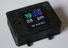
This repository contains the software and design files for my custom smartwatch thing. The system is built on an ESP32, and the software is written in C++, using ESP-IDF and Arduino. The software includes a few "apps", which are shown below.
The device uses a custom PCB that holds the ESP32, and all the other electronics that make the system work. The PCB was designed in KiCad, and the enclosure for the device was made in OpenSCAD.
The system isn't as powerful as existing smartwatches, but it was a really great way for me to learn a lot of electronics and programming concepts and tools. This isn't supposed to be a marketable product, but a proof of concept thing, and a way for me to develop my skills. This repository is here as a kind of archive to show the level my skills are at at time of writing, and hopefully as a thing to look back on and learn from.
 Watch Face |  Settings |  Calculator |  Stopwatch |
|---|---|---|---|
 Timer |  Alarms |  File Browser |  Notepad (read only) |
 IR Remote |  Image Viewer |  Weather |  Wikipedia |
 Quiz |  Music Player |  Internet Radio |  BLE Remote |
 Sensor Thing |  Tetris |  Snek 2 |  NES |
components ESP-IDF componentsdesign_files KiCad files for the schematic and PCBdocs documentation for the system (see docs/readme.md for more detail)extras other stuff like icons, data files, and pinout for the original breadboard prototypemain where all the code livesspiffs data and images for the SPIFFS partitionThese are some rough instructions for installing and flashing the software on to an ESP32 board. These steps are mainly aimed for Linux systems.
git clone this repository somewhere - git clone https://github.com/atctwo/watch-II.gitcd into the project directory
chmod +x install_libraries.sh
./install_libraries.shidf.py menuconfig to tell ESP IDF the flash size of the ESP32 you are using
Serial flasher config → Flash size and select the right flash size (i've only created partition files for 8MB and 16MB at the minute)Partition table → Custom partition CSV file and enter either partitions_8mb.csv or partitions_16mb.csvidf.py build, and to write the built firmware to an ESP32 board, run idf.py flash (see the ESP-IDF documentation for more detail on these commands)# if you're using an 8 MB flash
esptool.py --port /dev/ttyUSB0 write_flash 0x340000 spiffs/spiffs_8mb.bin
# if you're using a 16 MB flash
esptool.py --port /dev/ttyUSB0 write_flash 0xE20000 spiffs/spiffs_16mb.bin docs/notes/libraries.md| Qty | Value | Footprint | References |
|---|---|---|---|
| 7 | 0.1uF | Capacitor_SMD:C_0805_2012Metric | C1, C3, C5, C6, C7, C8, C9 |
| 6 | 1k | Resistor_SMD:R_0805_2012Metric | R1, R6, R10, R14, R17, R18 |
| 6 | TestPoint_Pad_D1.0mm | TestPoint:TestPoint_Pad_D1.0mm | BLK, D-, D+, DIN, DOUT, LRC |
| 5 | R | Resistor_SMD:R_0805_2012Metric | R11, R12, R13, R19, R20 |
| 4 | label | , , , | |
| 4 | MOUNTINGHOLE2.5 | MOUNTINGHOLE_2.5_PLATED | U$7, U$8, U$9, U$10 |
| 2 | 100R | Resistor_SMD:R_1210_3225Metric | R28, R31 |
| 2 | 100k | Resistor_SMD:R_0805_2012Metric | R25, R26 |
| 2 | 10k | Resistor_SMD:R_0805_2012Metric | R15, R27 |
| 2 | 10uF | Capacitor_SMD:C_0805_2012Metric | C2, C4 |
| 2 | 27R | Resistor_SMD:R_0805_2012Metric | R4, R5 |
| 2 | 330R | Resistor_SMD:R_0805_2012Metric | R30, R32 |
| 2 | 4k7 | Resistor_SMD:R_0805_2012Metric | R2, R3 |
| 2 | 5k1 | Resistor_SMD:R_0805_2012Metric | R7, R8 |
| 2 | Conn_01x03_Male | Connector_PinHeader_2.54mm:PinHeader_1x03_P2.54mm_Vertical | J4, J5 |
| 2 | Q_NPN_BCE | Package_TO_SOT_SMD:SOT-23 | Q2, Q3 |
| 2 | SW_Push | Button_Switch_SMD:SW_SPST_EVQP2 | SW2, SW2 |
| 1 | 2k | Resistor_SMD:R_0805_2012Metric | R9 |
| 1 | 680k | Resistor_SMD:R_0805_2012Metric | R24 |
| 1 | 68R | Resistor_SMD:R_0805_2012Metric | R29 |
| 1 | Battery_Cell | Connector_PinHeader_2.00mm:PinHeader_1x02_P2.00mm_Vertical | BT1 |
| 1 | ESP32-WROVER | Alice's Library:ESP32-WROVER | U7 |
| 1 | FT230XS | Package_SO:SSOP-16_3.9x4.9mm_P0.635mm | U1 |
| 1 | LC709203FQH-01TWG | Package_DFN_QFN:WDFN-8-1EP_4x3mm_P0.65mm_EP2.4x1.8mm | U3 |
| 1 | LED | LED_SMD:LED_0805_2012Metric_Castellated | D1 |
| 1 | LED_IR | Alice's Library:SOD4223X290N | D5 |
| 1 | LED_TORCH | Alice's Library:MLCAWT-A1-0000-000XE1 | D4 |
| 1 | MAX16150AUT+T | Package_TO_SOT_SMD:SOT-23-6 | U4 |
| 1 | MAX604 | Package_SO:SOIC-8-1EP_3.9x4.9mm_P1.27mm_EP2.29x3mm | U5 |
| 1 | MAX98357AETE+T | Package_DFN_QFN:QFN-16-1EP_3x3mm_P0.5mm_EP1.7x1.7mm | U8 |
| 1 | MCP23008-xSS | Package_SO:SSOP-20_5.3x7.2mm_P0.65mm | U6 |
| 1 | MCP73831-2-OT | Package_TO_SOT_SMD:SOT-23-5 | U2 |
| 1 | MCP9808_MSOP | Package_SO:MSOP-8_3x3mm_P0.65mm | U10 |
| 1 | Panasonic_EVQPUJ_EVQPUA | Button_Switch_SMD:Panasonic_EVQPUJ_EVQPUA | IO0 |
| 1 | PinHeader_1x02_P2.54mm_Vertical | Connector_PinHeader_2.54mm:PinHeader_1x02_P2.54mm_Vertical | Speaker |
| 1 | Power Button | Button_Switch_SMD:SW_SPST_EVQP2 | SW3 |
| 1 | RX | LED_SMD:LED_0805_2012Metric_Castellated | D3 |
| 1 | SPH0645LM4H-B | Alice's Library:MIC_SPH0645LM4H-B | MK1 |
| 1 | STEMMA QT | Connector_JST:JST_SH_SM04B-SRSS-TB_1x04-1MP_P1.00mm_Horizontal | J2 |
| 1 | Speaker | Alice's Library:XDCR_CMT-7525-80-SMT-TR | LS1 |
| 1 | TFT Connector | Connector_PinHeader_2.54mm:PinHeader_1x11_P2.54mm_Vertical | J6 |
| 1 | TSOP38238 | OptoDevice:Vishay_MINICAST-3Pin | U9 |
| 1 | TX | LED_SMD:LED_0805_2012Metric_Castellated | D2 |
| 1 | Torch Connector (daughter board) | Connector_PinHeader_2.54mm:PinHeader_1x02_P2.54mm_Vertical | J8 |
| 1 | Torch Connector (main board) | Connector_PinHeader_2.54mm:PinHeader_1x02_P2.54mm_Vertical | J7 |
| 1 | UART Connector | Connector_PinHeader_1.27mm:PinHeader_1x03_P1.27mm_Vertical | J3 |
| 1 | USB_C_Receptacle_USB2.0 | Alice's Library:JAE_DX07S016JA1R1500 | J1 |
The 84 most common of 86 parts.

antmicro/rdimm-ddr4-tester
Experimental platform built around Xilinx Kintex-7 FPGA for development and customization of RAM controllers supporting RDIMM DDR4 RAM modules used in data centers.


cuspaceflight/si4463-breakout
Breakout board for the Si4463 configured for 868 MHz

d3vf1x/MSN
Wireless Enviromental Sensor that can make use of multiple IoT technologies.


cuspaceflight/royale
Control and Instrumentation Systems for the White Giant test stand


oomlout/oomlout_oomp_project_bot_v_2
It measures 48.6 × 42.9 mm and has 2 copper layers, 1.6 mm thick.
86 parts, built around the ESP32-WROVER, FT230XS-R, MAX98357AETE+T and MAX16150AUT+T. The full list of its parts is on this page, with links to each part's symbol and footprint where PCBKit's library has them.
From the atctwo/watch-II repository on GitHub, at the commit this page was made from: the board is design_files/watch2_board/watch2-board-outline.kicad_pcb. PCBKit opens the board in the browser, with nothing to install.
Its repository publishes it under the MIT licence: you may reuse it on that licence's terms (keep the author's notice, and for a copyleft licence share your changes alike).