

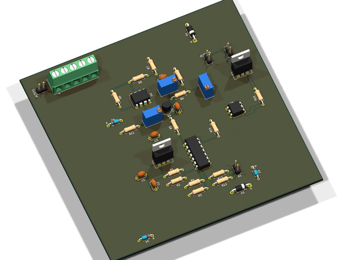
2 layers121.9 × 119.2 mm
VARIATEUR 0 10V
AssaadMH/power-electronics-simulation
AC power controllers, a 0–10 V industrial dimmer, a digital tachometer and a brushless drive, designed and simulated end to end.
39 parts1MIT

AC power controllers, a 0–10 V industrial dimmer, a digital tachometer and a brushless drive, designed and simulated end to end.
TACHYM is an open-source printed circuit board by AssaadMH, from the AssaadMH/power-electronics-simulation repository on GitHub, published under the MIT licence. It is a 2-layer board of 72.8 × 72.8 mm with 23 parts on 25 nets, routed with 187 tracks and 10 vias.
It is built around the PIC16F877A-I/P. Its parts include 7 resistors, 2 capacitors, 2 diodes, 2 transistors and 1 IC. It belongs with the PIC boards of this library.
AC power controllers, a 0–10 V industrial dimmer, a digital tachometer and a brushless drive, designed and simulated end to end.
2025·Proteus·Power electronics·Analog design·Microcontroller·PSIM
A body of power-electronics design work carried through schematic capture and full mixed-signal simulation before any board was built.
It covers phase-angle AC power controllers (including a capacitive-trigger variant), a 0–10 V industrial power regulator matching the standard control-signal interface used on drives and dimmable ballasts, a microcontroller-based digital tachometer, and a brushless motor drive — alongside characterisation work on transistor stages and power amplifiers.
Simulating first is the point: switching topologies punish the difference between a circuit that works on paper and one that survives a real inductive load.
captures/
docs/
kicad/docs/gradateur-0-10V-projet-tutore.pptx: the tutored-project defence for the 0-10 V power dimmer (ENIG, 2024/2025), by Mahmoudi Lassaad, Omri Salim and Dhaoui Chahin. It covers the 7812 supply, the LM358 stage, the PWM power control, the simulation and the PCB. The related boards are kicad/VARIATEUR_0_10V/ and kicad/GRADATEUR_DE_PUISSANCE/.Everything in this repository is my own work. It builds on the following, which are not mine and are used under their own licences:
Lassaad Mahmoudi — assaadmahmoudi0@gmail.com
https://linkedin.com/in/mahmoudi-assaad
| Qty | Value | Footprint | References |
|---|---|---|---|
| 6 | 10k | Resistor_THT:R_Axial_DIN0207_L6.3mm_D2.5mm_P10.16mm_Horizontal | R1, R2, R3, R5, R6, R7 |
| 2 | 1N4007 | Diode_THT:D_DO-41_SOD81_P10.16mm_Horizontal | D1, D2 |
| 2 | 22pF | Capacitor_THT:C_Disc_D5.0mm_W2.5mm_P5.00mm | C1, C2 |
| 2 | 2N2222 | Package_TO_SOT_THT:TO-18-3 | Q1, Q2 |
| 1 | 10k | Connector_PinHeader_2.54mm:PinHeader_1x03_P2.54mm_Vertical | RV3 |
| 1 | 1K | Connector_PinHeader_2.54mm:PinHeader_1x03_P2.54mm_Vertical | RV1 |
| 1 | 1k | Resistor_THT:R_Axial_DIN0207_L6.3mm_D2.5mm_P10.16mm_Horizontal | R4 |
| 1 | 2000 | Connector_PinHeader_2.54mm:PinHeader_1x03_P2.54mm_Vertical | RV4 |
| 1 | 2k | Connector_PinHeader_2.54mm:PinHeader_1x03_P2.54mm_Vertical | RV2 |
| 1 | 5V | Connector_PinHeader_2.54mm:PinHeader_1x02_P2.54mm_Vertical | B2 |
| 1 | 80 | Connector_PinHeader_2.54mm:PinHeader_1x02_P2.54mm_Vertical | B1 |
| 1 | B125C1000 | Diode_THT:Diode_Bridge_19.0x3.5x10.0mm_P5.0mm | BR1 |
| 1 | CRYSTAL | Crystal:Crystal_HC49-U_Vertical | X1 |
| 1 | LCD 2X16 | Connector_PinHeader_2.54mm:PinHeader_1x16_P2.54mm_Vertical | LCD2 |
| 1 | PIC16F877A | Package_DIP:DIP-40_W15.24mm | U1 |
AssaadMH/power-electronics-simulation
AC power controllers, a 0–10 V industrial dimmer, a digital tachometer and a brushless drive, designed and simulated end to end.

AssaadMH/power-electronics-simulation
AC power controllers, a 0–10 V industrial dimmer, a digital tachometer and a brushless drive, designed and simulated end to end.

AssaadMH/power-electronics-simulation
AC power controllers, a 0–10 V industrial dimmer, a digital tachometer and a brushless drive, designed and simulated end to end.

AssaadMH/power-electronics-simulation
AC power controllers, a 0–10 V industrial dimmer, a digital tachometer and a brushless drive, designed and simulated end to end.


Rishvanth-SK-2002/8051-Digital-Clock
Bare-metal 8051 digital clock and alarm with custom KiCad PCB and assembly firmware.


google/mozc-devices
Circuit diagrams and firmware source code for Gboard DIY keyboards


It measures 72.8 × 72.8 mm and has 2 copper layers, 1.6 mm thick.
23 parts, built around the PIC16F877A-I/P. The full list of its parts is on this page, with links to each part's symbol and footprint where PCBKit's library has them.
From the AssaadMH/power-electronics-simulation repository on GitHub, at the commit this page was made from: the board is kicad/TACHYM/TACHYM.kicad_pcb. PCBKit opens the board in the browser, with nothing to install.
Its repository publishes it under the MIT licence: you may reuse it on that licence's terms (keep the author's notice, and for a copyleft licence share your changes alike).