4 layers239.4 × 165.7 mm

 aslak3/MAXI03038
MC68030 based expandable computer design
Spreadout is an open-source printed circuit board by aslak3, from the aslak3/MAXI030 repository on GitHub, published under the GPL-2.0 licence. It is a 4-layer board of 239.4 × 165.7 mm with 199 parts on 441 nets, routed with 7,565 tracks and 880 vias.
It is built around the MC68030RC16C, 74HCT245 and 74HC245D, with the MAX238EWG+, RTL8019AS-LF and SR05S05 among its other parts. Its parts include 78 capacitors, 34 resistors, 34 ICs, 15 connectors and 4 diodes. It belongs with the fPGA and programmable logic boards and the FPGA and CPLD boards of this library.


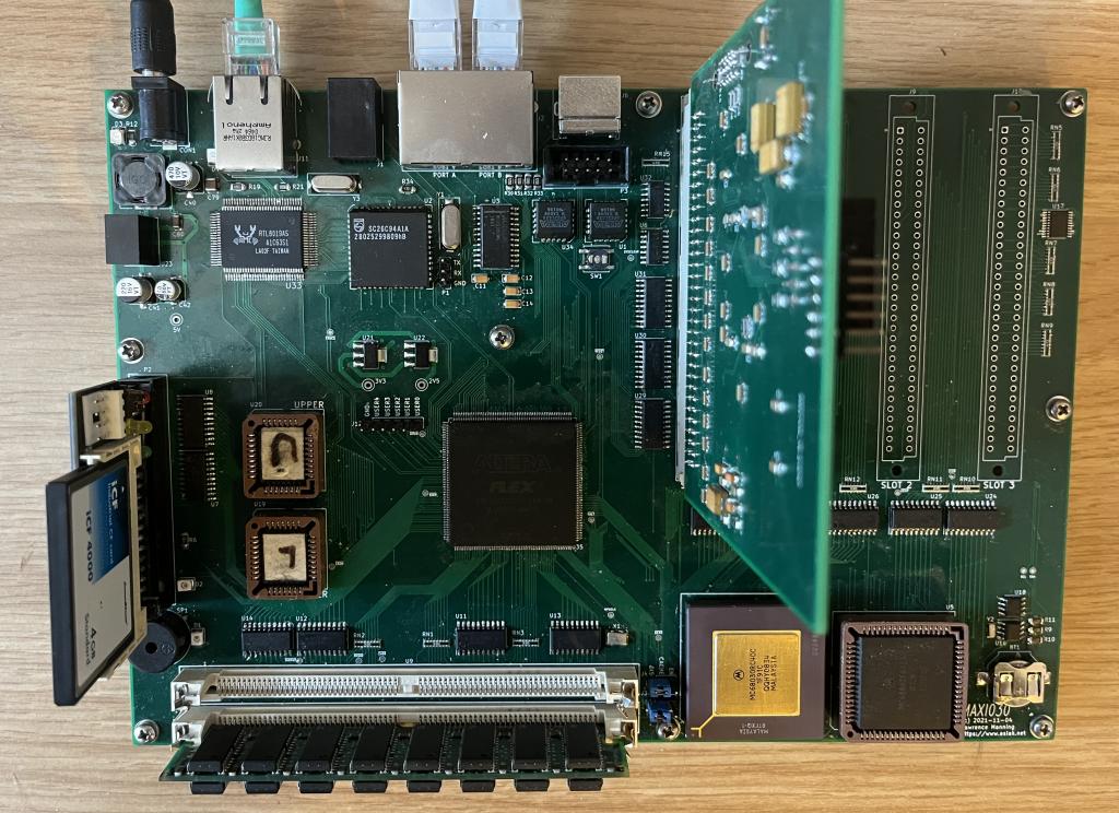
The specification for MAXI030, a MC68030 based computer, is as follows:
A schematic is included here, along with the KiCAD data files. Note that schematic symbols are included in the library cache. Whilst these boards were designed with KiCAD 4, the files in this repository are all KiCAD 6 format.
The PCB is a 4 layer board. The requirements to make the board are quite heavy; 6 mil traces are used, with 6.5 mil clearances between them. 3 traces pass between 100mil spaced pins in multiple places. My boards were manufactured by JLCPCB with no issues.
A major feature of this board is the EPF10K130EQC240 FPGA. This component is part of Altera's Flex 10KE family, which is a 3.3V/2.5V part descended from the Flex 10K line of 5V parts. These FPGAs are unfortunately obsolete, and difficult to get hold of; I sourced mine from UTSource.
The board uses mixed 3.3V and 5V signaling. The Flex 10KE series is "special" in that it is fully 5V tolerant without an inline resistor, unlike later Altera parts such as the early Cylcones which are 5V tolerant but need an inline resistor. The Flex 10KE also have outputs compatible with 5V TTL levels. My previous projects have made heavy use of the 5V Flex 10K parts, but I have found that as the board frequency has increased, these FPGAs have reached their limit. Consequently this board switched to the Flex 10KE, despite the complexities inherent in a mixed signal level board.
Beside getting hold of the actual part a challenge facing anyone building this board is obtaining a compatible Altera Quartus version since Intel have, in their wisdom, removed from their site the 9.0sp2 version; the last that supported the Flex 10K(E) series. It can still be obtained if you know where to look, however.
Another small annoyance, related to the FPGA side of the board, is that two EPC2 configuration flashes are needed since this is a large, for the time, FPGA.
I have implemented the following functionality, all in VHDL:
The code for this functionality resides in the MAXI030Core directory, where a more detailed description of the files used can be found.
As this is FPGA hardware, many other things could be implemented. In particular, the FPGA is wired to the full 32 bits of address and data, so a bus-mastering DMA controller could be constructed. This could be used for disk transfers, amongst other things, which would greatly speed up these operations. The interrupt handling is also basic at present, and vectored interrupts should probably be used.
It's worth pointing out, for completeness, that since the FPGA is attached to a 32 bit wide by 4GB address space it would theoretically be possible to use this board to replace the 68030 with some other custom softcore processor running inside the FPGA, with the 68030 disabled or simply not present. Perhaps a more interesting opportunity would be to implement a custom 68020+ style co-processor.
The following three cards have been created:
The TestxSRAM card (such as it is) has been shown to be error-free. The Printer+Joystick card has been exercised by attaching an old 9 pin dot matrix printer and printing text, though this was with the earlier MIDI020 68020 board. The Video+Sound board has been attached to MAXI030 and, though it has a few teaming troubles, it appears to work well. The sound portion of that card has not been explored at all however.
More documentation on these cards will be forthcoming. For now, each expansion card directory contains the schematic and PCB files in KiCAD format, plus a PDF of the schematic, the BOM, and the rendered gerbers used to produce the cards.
Over the years I've extended my monitor to run on each 68K based board as I've produced them. The monitor is basic, but serviceable. It is in no way designed for software development; it's main purpose is to exercise the hardware. It has low-level (memory/IO operations) and high level functionality:
It is also used to start the Linux kernel.
The monitor source is held in its own repository.
A Linux port has been started and seems to work quite well. The following hardware has been shown to work, by making very small changes to existing drivers or creating new ones:
With a 32MHz can installed, a modern Linux kernel will boot in about 2.5 minutes. But see the Gotchas section below.
A fork of the Linux kernel from early 2022 has work done at the head of the lm/maxi030 branch with the changes I've made.
The userland I'm currently using is based on a very old Debian build, even though the kernel is almost the latest, since running the latest 68k Debian packages results in a very slow system. This is another thing to investigate.
A script, which is a total hack, for generating an directory tree of Debian Linux is available in the linux directory. This script can generate both sid (current) and sarge (old) Debian images. It must be edited before use to set the DNS resolver, interface addressing, passwords, custom packages and other things. It makes use of multistrap and QEUMU's 68K support to do its thing.
As it currently stands, the Linux system is useable across the UART (via a login getty), and via the network. Both SSH and telnet are available, SSH being extremely slow as predicted. Console access, using the PS/2 port and my bitmap video card, is very much a work in progress, though I did have X running (very, very slowly) at one point.
The general process to get Linux running on MAXI030 is as follows, assuming the board is up and running with the monitor available via a UART port:
The big issue I'm currently working on is board speed. With all the functionality enabled in the FPGA design, I'm currently not able to run the board at the maximum speed of the 68030 I have installed, 40MHz. Insteaed I must settle for running the board at 32MHz. In particular adding the FIFOs on the PS/2 controller results in an inoperable system at 40MHz. The FIFOs seem to be required when running in Linux since the kernel disables interrupts in some situations, which results in data loss.
The board also has a few very minor problems:
The best place to learn about this board is undoubtably my blog, including these posts:
I've also made a short YouTube video, which discusses the board and demos the Linux port.
| Qty | Value | Footprint | References |
|---|---|---|---|
| 61 | 0.1u | Capacitor_SMD:C_1206_3216Metric | C1, C2, C15, C16, C17, C18, C19, C20, C21, C22, C23, C24, C25, C26, C27, C28 +45 |
| 15 | 4.7K | Resistor_SMD:R_1206_3216Metric | R1, R4, R5, R6, R8, R9, R10, R11, R13, R14, R15, R16, R28, R29, R34 |
| 11 | 1K | Resistor_SMD:R_1206_3216Metric | R2, R3, R7, R12, R20, R22, R23, R24, R25, R26, R27 |
| 10 | 74HCT245 | SOs:SO-20_5.3x12.6mm_P1.27mm | U7, U8, U24, U25, U26, U27, U28, U29, U30, U31 |
| 9 | MountingHole_Pad | MountingHole:MountingHole_3.2mm_M3_Pad | H1, H2, H3, H4, H5, H6, H7, H8, H9 |
| 8 | 33 | Resistor_SMD:R_Cat16-8 | RN1, RN2, RN3, RN10, RN11, RN12, RN13, RN14 |
| 5 | 10K | Resistor_SMD:R_Cat16-8 | RN5, RN6, RN7, RN8, RN9 |
| 4 | 1.0u | Capacitor_Tantalum_SMD:CP_EIA-3216-18_Kemet-A | C11, C12, C13, C14 |
| 4 | 120 | Resistor_SMD:R_1206_3216Metric | R30, R31, R32, R33 |
| 4 | 22p | Capacitor_SMD:C_1206_3216Metric | C9, C10, C57, C58 |
| 4 | 74HC245 | SOs:SO-20_5.3x12.6mm_P1.27mm | U11, U12, U13, U14 |
| 4 | DIN_41612_3x32_MIDI020_EXP | aslakfp:DIN41612_C_2x32_Female_Vertical_THT | J7, J8, J9, J10 |
| 3 | 10u | Capacitor_Tantalum_SMD:CP_EIA-3216-10_Kemet-I | C36, C37, C39 |
| 2 | 10n | Capacitor_SMD:C_1206_3216Metric | C59, C60 |
| 2 | 4.7K | Resistor_SMD:R_Cat16-8 | RN4, RN15 |
| 2 | Conn_01x03 | Connector_PinHeader_2.54mm:PinHeader_1x03_P2.54mm_Vertical | J3, J4 |
| 2 | EPC2 | Package_LCC:PLCC-20 | U1, U34 |
| 2 | SIM72Pin | aslakfp:SIMM72Pins | U9, U10 |
| 2 | SST39SF040-PC32 | Package_LCC_local:PLCC-32_THT-Socket | U19, U20 |
| 1 | 10K | Resistor_SMD:R_1206_3216Metric | R19 |
| 1 | 10u | Capacitor_SMD:CP_Elec_5x5.7 | C42 |
| 1 | 1M | Resistor_SMD:R_1206_3216Metric | R18 |
| 1 | 200 | Resistor_SMD:R_1206_3216Metric | R21 |
| 1 | 20M | Crystal:Crystal_SMD_HC49-SD | Y3 |
| 1 | 220u | Capacitor_SMD:CP_Elec_6.3x7.7 | C41 |
| 1 | 27K | Resistor_SMD:R_1206_3216Metric | R17 |
| 1 | 2V5 | TestPoint:TestPoint_Loop_D1.80mm_Drill1.0mm_Beaded | TP2 |
| 1 | 32.768 | Crystal:Crystal_SMD_EuroQuartz_EQ161-2Pin_3.2x1.5mm | Y2 |
| 1 | 3V3 | TestPoint:TestPoint_Loop_D1.80mm_Drill1.0mm_Beaded | TP1 |
| 1 | 470u | Capacitor_SMD:CP_Elec_6.3x7.7 | C40 |
| 1 | 47u | Capacitor_Tantalum_SMD:CP_EIA-7343-15_Kemet-W | C34 |
| 1 | 5V | TestPoint:TestPoint_Loop_D1.80mm_Drill1.0mm_Beaded | TP3 |
| 1 | 68882 | Package_LCC:PLCC-68_THT-Socket | U5 |
| 1 | 7.3728M | Crystal:Crystal_SMD_HC49-SD | Y1 |
| 1 | 74LS03 | Package_SO:SOIC-14_3.9x8.7mm_P1.27mm | U6 |
| 1 | 74LS21 | Package_SO:SOIC-14_3.9x8.7mm_P1.27mm | U32 |
| 1 | AZ1117-2.5 | Package_TO_SOT_SMD:SOT-223-3_TabPin2 | U22 |
| 1 | AZ1117-3.3 | Package_TO_SOT_SMD:SOT-223-3_TabPin2 | U21 |
| 1 | BUZZER | Buzzer_Beeper:Buzzer_15x7.5RM7.6 | SP1 |
| 1 | Battery_Cell | Battery:BatteryHolder_Keystone_3000_1x12mm | BT1 |
| 1 | CONN_02X20_IDE | Connector_IDC:IDC-Header_2x20_P2.54mm_Vertical | P2 |
| 1 | CORELED | LED_SMD:LED_1210_3225Metric | D1 |
| 1 | Conn_01x06 | Connector_PinHeader_2.54mm:PinHeader_1x06_P2.54mm_Vertical | J12 |
| 1 | DS1307Z+ | Package_SO:SOIC-8_3.9x4.9mm_P1.27mm | U18 |
| 1 | DUALRJ45_RS232 | local:DUALRJ45 | J2 |
| 1 | EPF10K130EQC240 | Package_QFP:PQFP-240_32.1x32.1mm_P0.5mm | U35 |
| 1 | IDELED | LED_SMD:LED_1210_3225Metric | D2 |
| 1 | JTAG | Connector_IDC:IDC-Header_2x05_P2.54mm_Vertical | P3 |
| 1 | LED | LED_SMD:LED_1210_3225Metric | D4 |
| 1 | LM75A | Package_SO:SO-8_3.9x4.9mm_P1.27mm | U16 |
| 1 | MAX238 | Package_SO:SOIC-24W_7.5x15.4mm_P1.27mm | U3 |
| 1 | MC68030RC | kiss68030:PGA128 | U4 |
| 1 | MPUOSC | Oscillator:Oscillator_SMD_SeikoEpson_SG8002CA-4Pin_7.0x5.0mm | X1 |
| 1 | Mini-DIN-6 | aslakfp:Connector_Mini-DIN_Female_6Pin_2rows | J6 |
| 1 | PCA9544APW | Package_SO:TSSOP-20_4.4x6.5mm_P0.65mm | U17 |
| 1 | POWERLED | LED_SMD:LED_1210_3225Metric | D3 |
| 1 | POWERLJACK | Connector_BarrelJack:BarrelJack_Horizontal | CON1 |
| 1 | RESETBUTTON | Button_Switch_SMD:SW_Push_1P1T_NO_CK_KSC6xxJ | SW1 |
| 1 | RJ10_KEYBOARD | aslakfp:RJ10 | J1 |
| 1 | RJ45_Amphenol_RJMG1BD3B8K1ANR | Connector_RJ:RJ45_Amphenol_RJMG1BD3B8K1ANR | J11 |
| 1 | RTL8019AS | aslakfp:RTL8019AS | U33 |
| 1 | SC26C94 | Package_LCC:PLCC-52 | U2 |
| 1 | SR05S05 | Converter_DCDC:Converter_DCDC_RECOM_R-78E-0.5_THT | U23 |
| 1 | TTL_SERIAL | Connector_PinHeader_2.54mm:PinHeader_1x03_P2.54mm_Vertical | P1 |
It measures 239.4 × 165.7 mm and has 4 copper layers, 1.6 mm thick.
199 parts, built around the MC68030RC16C, 74HCT245, 74HC245D and MAX238EWG+. The full list of its parts is on this page, with links to each part's symbol and footprint where PCBKit's library has them.
From the aslak3/MAXI030 repository on GitHub, at the commit this page was made from: the board is spreadout.kicad_pcb and its schematic Ethernet.kicad_sch. PCBKit opens the board in the browser, with nothing to install.
Its repository publishes it under the GPL-2.0 licence: you may reuse it on that licence's terms (keep the author's notice, and for a copyleft licence share your changes alike).


crmaykish/mackerel-68k
A series of single-board Motorola 68k computers with support for modern Linux


transistorfet/retroverse
A collection of VME-based hardware and software for modular computers


mggates39/68hc11_SBC
Building a Single Board Computer around the MC68HC11. It will include my first attempt with KiCad designing a PCB

Trilobyte-CPU/8-bit-computer
A DIY 8-bit computer built mostly with discrete logic chips