Skip to the content
2 layers16 × 16 mmKorry pcb v2, the printed circuit board in 3D

A custom-built modular home cockpit system for flight simulation, focused on replicating real aircraft controls using PCB design, CAD modeling, and embedded systems.

Size
16 × 16 mm
Copper layers
2
Thickness
1.6 mm
Parts
6
Nets
10
Pads
18
Tracks, vias
26, 0
Routed
Yes
KiCad
KiCad 9.0 (file 20241229)
Created
3 Apr 2026
Updated
29 Oct 2026

Overview

Korry pcb v2 is an open-source printed circuit board by aryanma11ick, from the aryanma11ick/Home_Cockpit_Project repository on GitHub. It is a 2-layer board of 16 × 16 mm with 6 parts on 10 nets, routed with 26 tracks and 0 vias.

It is built around the TL2230EEF140. Its parts include 2 resistors, 2 diodes, 1 connector and 1 switch.

Main components

1

README

README.md

🛫 Home Cockpit System

A custom-built modular home cockpit system for flight simulation, focused on replicating real aircraft controls using PCB design, CAD modeling, and embedded systems.

This project combines hardware engineering + software integration to create a scalable and realistic cockpit environment.


✈️ Overview

The goal of this project is to design a high-fidelity, modular cockpit system that closely mimics real aircraft panels while remaining flexible for expansion.

Key design principles:

  • 🔧 Modularity – Panels can be developed and used independently
  • 🧩 Scalability – Easy to expand into a full cockpit
  • 🎯 Realism – Accurate switch behavior and layout
  • ⚡ Integration – Seamless connection with flight simulators

🧱 Project Structure

text
hardware/
├── pcb/          # KiCad design files + Gerbers
└── cad/          # STEP/STL files for panels and components

firmware/         # Microcontroller code (Arduino / ESP32)

software/         # Simulator interface plugins (X-Plane, etc.)

docs/             # Documentation, diagrams, and images

🔧 Modules

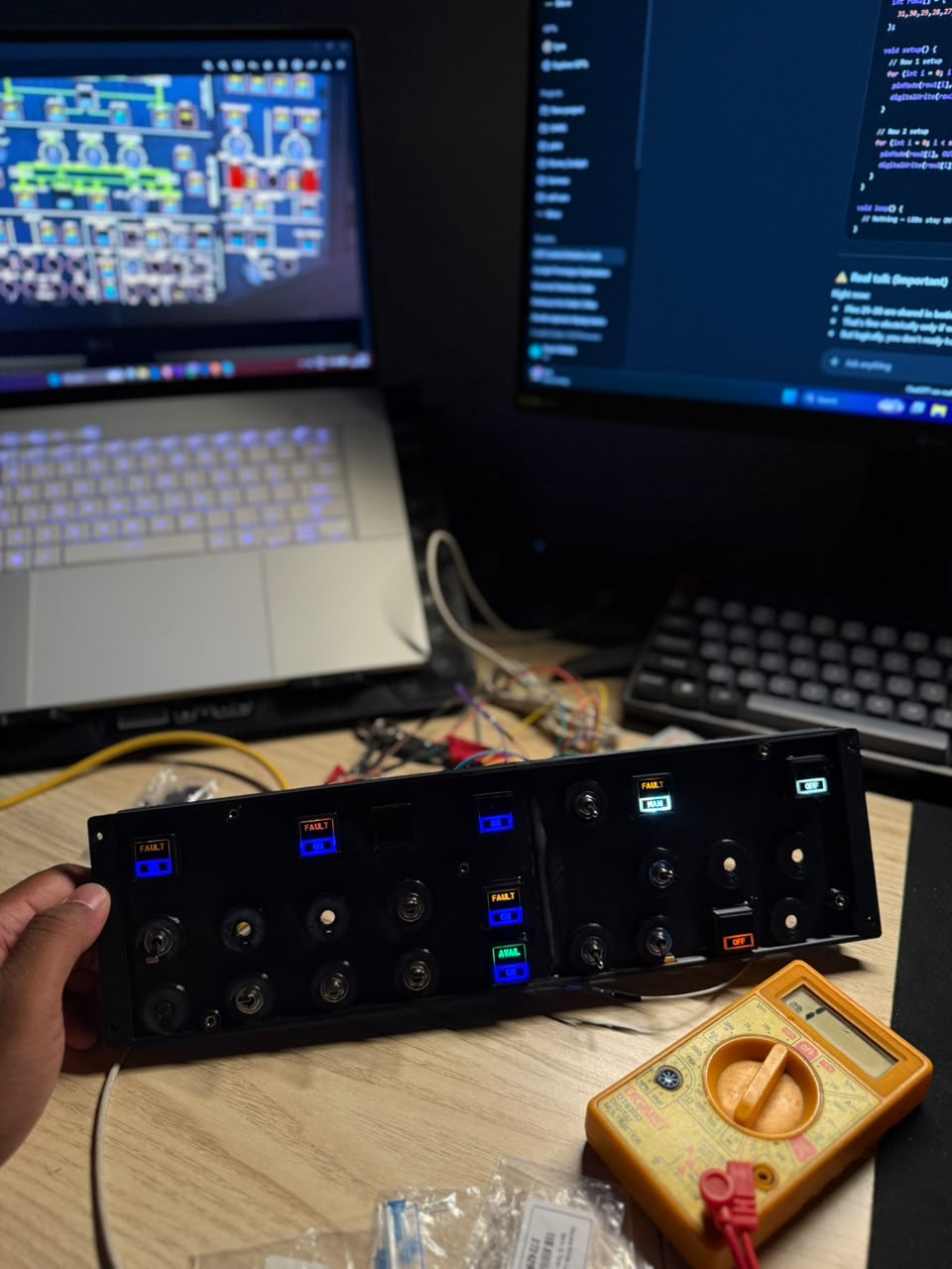
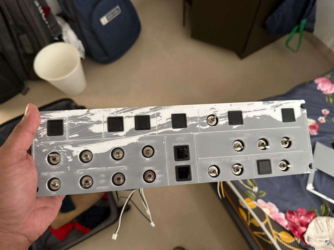
🟢 Overhead External Lights Panel

  • Fully functional external lighting control panel
  • Supports multiple 3-position and 2-position switches
  • Integrated with simulator via custom plugin
  • Designed for real-time hardware ↔ simulator synchronization

🟡 Annunciator (Alert) Panel

  • Displays aircraft alerts and system states
  • Uses custom illuminated switches
  • Modular layout for future expansion

🔘 Korry Switch Module (v2)

  • Custom PCB designed in KiCad
  • LED backlighting support
  • Reusable module for multiple panels
  • Includes CAD models for enclosure and mounting

⚙️ Technologies Used

🧠 Hardware

  • KiCad – PCB design and layout
  • Fusion 360 / CAD tools – Mechanical design and panel modeling

💻 Software

  • C++ (X-Plane SDK) – Simulator interface plugins
  • Arduino / ESP32 – Firmware and hardware control

🔗 Tools

  • GitHub – Version control and project management

🔁 System Architecture

text
[Physical Switches] → [Microcontroller] → [Serial Communication]
                                  ↓
                            [Plugin / Interface]
                                  ↓
                             [Flight Simulator]
                                  ↑
                          [DataRef Feedback Loop]
  • Closed-loop system ensures hardware and simulator stay synchronized
  • Supports real-time control and feedback

🚧 Project Status

Status: 🟢 Active Development

✅ Completed

  • Korry Switch PCB (v2)
  • Initial CAD panel designs
  • Overhead external lights panel (hardware + integration)

🔄 In Progress

  • Firmware refinement
  • Panel integration and wiring
  • Simulator interface improvements

📸 Media

Hardware Preview


🚀 Future Plans

  • Enhanced backlighting and light diffusion
  • Full overhead panel completion
  • Additional cockpit modules (FCU, MCDU, etc.)
  • Improved simulator integration and feedback systems
  • Expansion to a complete cockpit build

👤 Author

Aryan Mallick Building a full-scale home cockpit system from scratch


⭐ Notes

This project is continuously evolving with improvements in:

  • Hardware design
  • Firmware reliability
  • Simulator integration

Contributions, suggestions, and feedback are welcome.

Parts

6
QtyValueFootprintReferences
2LEDLED_THT:LED_Rectangular_W5.0mm_H2.0mmD1, D2
2RResistor_SMD:R_0805_2012Metric_Pad1.20x1.40mm_HandSolderR1, R2
1Conn_01x04_PinConnector_PinHeader_2.54mm:PinHeader_1x04_P2.54mm_VerticalJ1
1TL2230EEF140My_Footprints:SW_TL2230EEF140S1

Similar boards

  • 4 layers213.4 × 138.9 mmCapstone Project Smart glasses for the visually impaired, the printed circuit board in 3D

    Capstone Project Smart glasses for the visually impaired

    heyitsarthur/Capstone-Project-Smart-glasses-for-the-visually-impaired

    The system operates on a distributed architecture split between a head-mounted sensor array and a chest-mounted compute module. Main Computing Unit: Raspberry Pi Compute Module 4 (CM4) running on a custom PCB.

    197 parts1
  • 2 layers70.3 × 11.5 mmTigsich, the printed circuit board in 3D

    Tigsich

    tdarlic/tigsich

    TIGSICH – finger remote for IPOTools SuperTIG 200Di TIG machine

    5 parts
  • 2 layers18.5 × 11.1 mmSwitch, the printed circuit board in 3D

    Switch

    byrantech/laptop

    anyon_e, a highly integrated, high end, open source laptop. Attempt the impossible.

    6 parts4.3kMIT
  • 2 layers14.6 × 33 mmBrain board SD Card 1, the printed circuit board in 3D

    Brain board SD Card 1

    rusefi/rusefi

    rusefi - GPL internal combustion engine control unit

    6 parts1.2k
  • 2 layers9 × 9 mmDpoint, the printed circuit board in 3D

    Dpoint

    Jcparkyn/dpoint

    Open-source digital stylus using camera tracking and inertial measurements

    6 parts1.1kMIT
  • 2 layers51.5 × 16.6 mmMicroswitchXY Endstop, the printed circuit board in 3D

    MicroswitchXY Endstop

    VoronDesign/Voron-Hardware

    Cool Hardware designed by the Voron Design group

    6 parts1.1kGPL-3.0
  • 2 layers21.9 × 76.7 mmAmiga External, the printed circuit board in 3D

    Amiga External

    hoglet67/RGBtoHDMI

    Bare-metal Raspberry Pi project that provides pixel-perfect sampling of Retro Computer RGB/YUV video and conversion to HDMI

    6 parts1kGPL-3.0
  • 2 layers88.9 × 50.8 mmBusinesscard, the printed circuit board in 3D

    Businesscard

    hackclub/OnBoard

    💡 Join 1,000 teenagers and make your first PCB with a $100 grant!

    6 parts915

Questions

How big is the Korry pcb v2 PCB?

It measures 16 × 16 mm and has 2 copper layers, 1.6 mm thick.

What parts does the Korry pcb v2 use?

6 parts, built around the TL2230EEF140. The full list of its parts is on this page, with links to each part's symbol and footprint where PCBKit's library has them.

Where can I download the Korry pcb v2 KiCad files?

From the aryanma11ick/Home_Cockpit_Project repository on GitHub, at the commit this page was made from: the board is hardware/pcb/kicad/korry_switch/korry_pcb_v2.kicad_pcb and its schematic hardware/pcb/kicad/korry_switch/korry_pcb_v2.kicad_sch. PCBKit opens the board in the browser, with nothing to install.

Can I use the Korry pcb v2 design in my own project?

Its repository states no licence, so its author keeps all rights: ask aryanma11ick before reusing the design.