
2 layers
Beehive
waterclear1/BeehiveMonitor_Hardware
Hardware for BeehiveMonitor project, made with Kicad
40 parts

 Aryan-git-byte/Soil-metrics1
Portable AI-powered soil monitoring device with LTE connectivity, GPS, touchscreen interface, and real-time soil health analytics.
Soil metrics is an open-source printed circuit board by Aryan-git-byte, from the Aryan-git-byte/Soil-metrics repository on GitHub, published under the MIT licence. It is a 4-layer board of 88.3 × 112.3 mm with 74 parts on 146 nets, routed with 2,566 tracks and 151 vias.
It is built around the ESP32-S3-WROOM-1U-N4, MAX3485ED and SIM7080G, with the MP2307DN-Z, THD2528-11SD-GF and CDRH104R-220NC among its other parts. Its parts include 21 capacitors, 20 resistors, 10 ICs, 6 diodes and 6 connectors. It belongs with the ESP32 boards of this library.



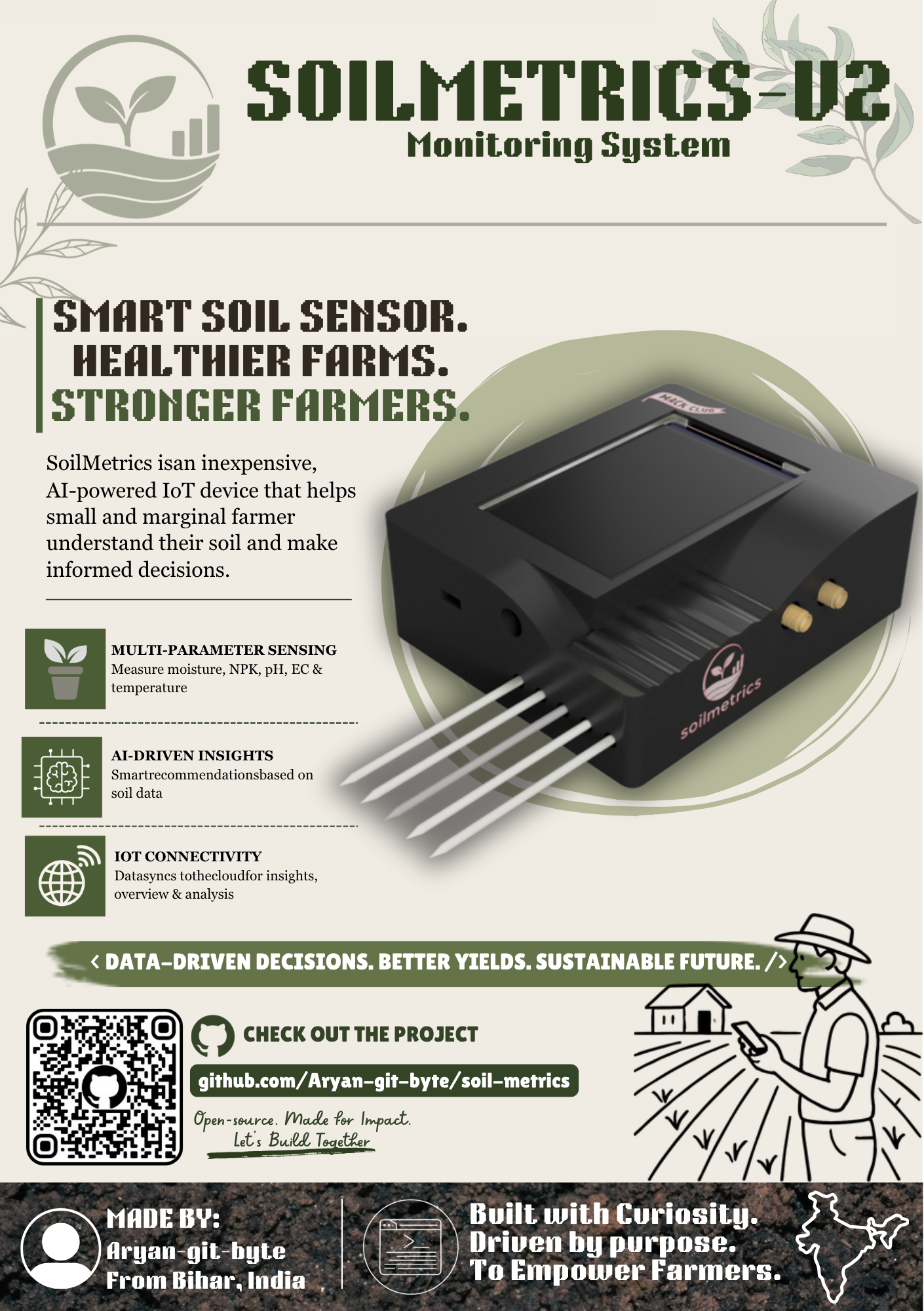
SoilMetrics is an affordable soil health monitoring system to measure key soil parameters in real time such as NPK, EC, pH, Moisture, and Temperature. which will allow small farmers to make scientific decision regarding their soil health and conditions which can help them do sustainable farming.
This device can measure soil moisture, temperature, pH, electrical conductivity, and NPK. and then can send all that data to a cloud server using LTE. it also offers on device touch display to view sensor readings, ai reccomendations, weather reports etc. with help of offline sd card based data logging, and rechargeable 2S 18650 its a near perfect solution to deploy on farmsites for primary soil health monitoring.
SoilMetrics/
│
├── assets/   images
├── cad/       CAD source files & exports
├── firmware/       ESP-IDF firmware
├── kicad/          kicad source file
├── production/     BOM & gerber
│
├── README.md
├── LICENSE
└── JOURNAL.md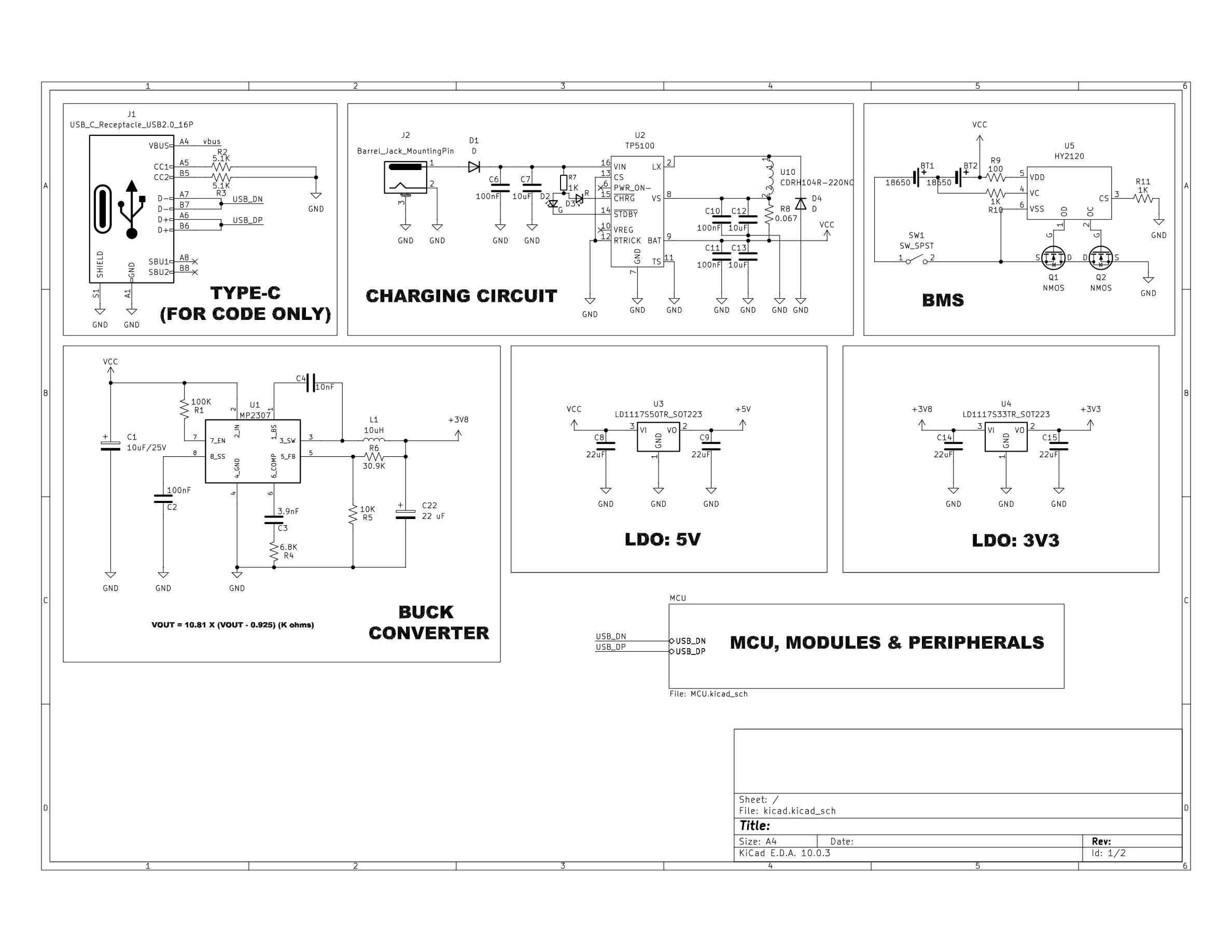
Contains all the power realted things of the device including Type-c for programming, barrel jack for charging, BMS circuitory, Buck Converter and LDOs
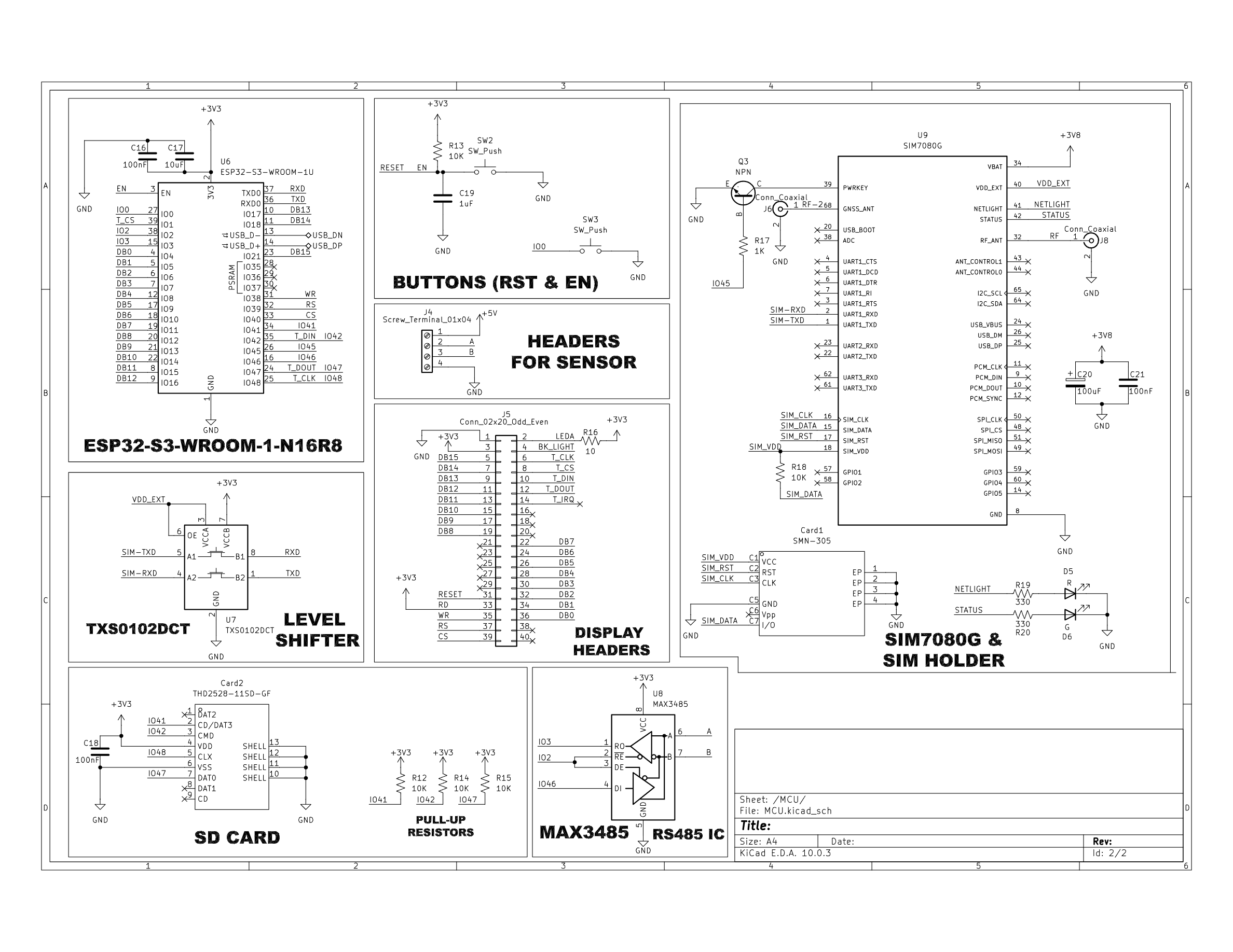
Contains the MCU, Buttons, LTE module, Receiver, SD card, sim slot etc
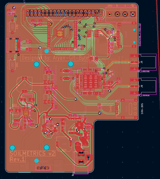
The hardware is designed on a 4 layer PCB, The complete design files are available here
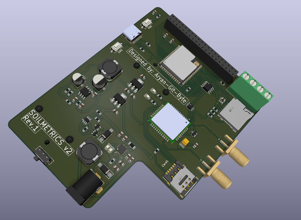
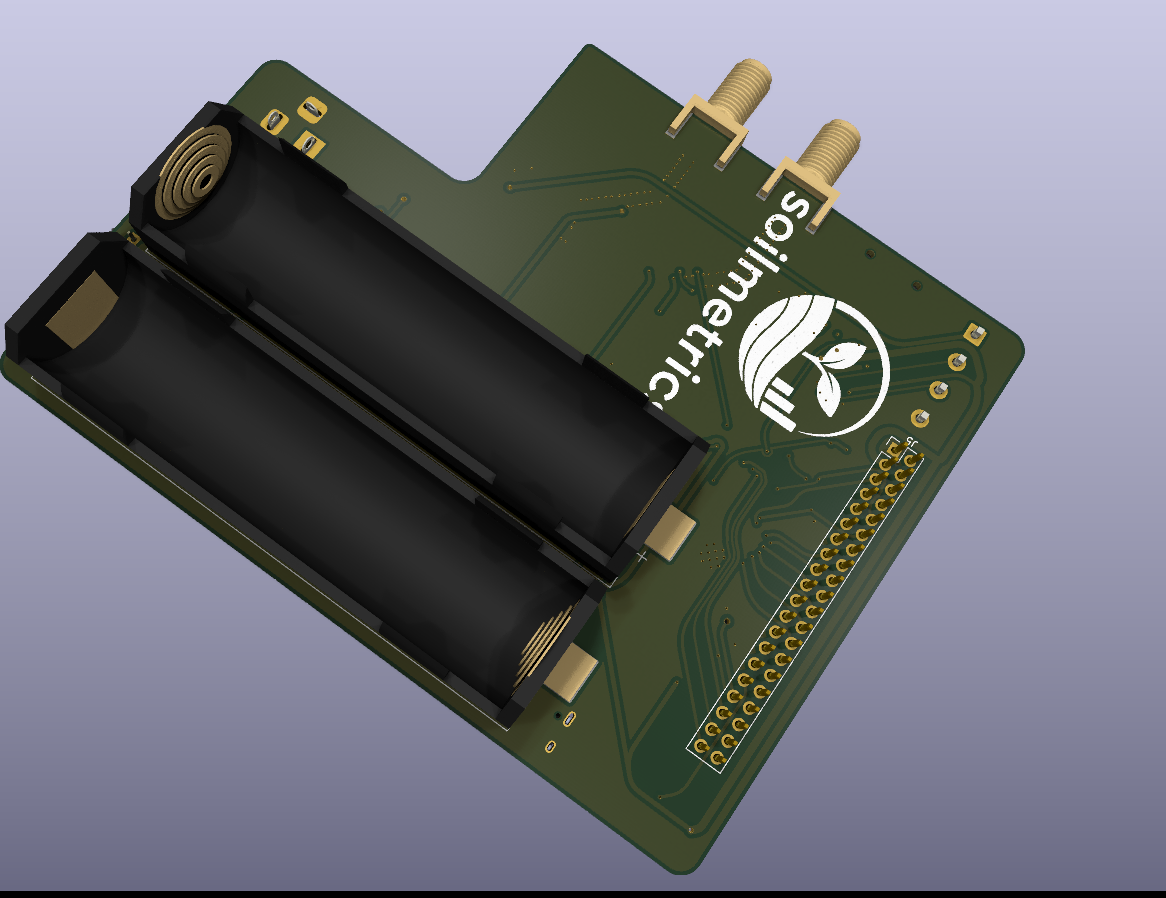
| File | Download Link | Description |
|---|---|---|
| Top Body Enclosure | here | This is the source file of the top body |
| Bottom plate | here | This is the source file of the Bottom plate |
| Top Body Enclosure | here | This is the printable file of the top body |
| Top Body Enclosure | here | This is the printable file of the top body |
Note: The complete firmware is not available as of now, there are lot of things that can only be written after making actual hardware, so i will update the repo with complete firmware after build. For now its just a test code.
Configure ESP-IDF
idf.py set-target esp32s3Build
idf.py buildConnect the board using USB.
Flash
idf.py flashOpen Serial Monitor
idf.py monitorIf flashing fails, place the board into download mode according to your ESP32-S3 hardware design and retry the command.
Enclosure is not complete yet due to the online unavailability of 3d model of the Display. After getting the display i'll update the repo with correct files
The completed BOM of the components used on PCB is in production/bom.csv.
And expect those you need to order these:
| Component | Link | Price |
|---|---|---|
| SmartElex 3.5" TFT Resistive Touch Display 320x480 | here | 917 rs |
| ZTS-3002-TR-*-N01 | here | 4396 rs |
| 2 x 18650 batteries | here | 699 rs each |
| PCB + Stencil | Sub-8K rs |
Made with 🔬🧪 (science) by aryan-git-byte
# AI USE: AI has assisted me in firmware/| Qty | Value | Footprint | References |
|---|---|---|---|
| 7 | 100nF | Capacitor_SMD:C_0805_2012Metric_Pad1.18x1.45mm_HandSolder | C2, C6, C10, C11, C16, C18, C21 |
| 6 | 10K | Resistor_SMD:R_0805_2012Metric_Pad1.20x1.40mm_HandSolder | R5, R12, R13, R14, R15, R18 |
| 4 | 10uF | Capacitor_SMD:C_0805_2012Metric_Pad1.18x1.45mm_HandSolder | C7, C12, C13, C17 |
| 4 | 1K | Resistor_SMD:R_0805_2012Metric_Pad1.20x1.40mm_HandSolder | R7, R10, R11, R17 |
| 4 | 22uF | Capacitor_SMD:C_0805_2012Metric_Pad1.18x1.45mm_HandSolder | C8, C9, C14, C15 |
| 2 | 18650 | Battery:BatteryHolder_Keystone_1042_1x18650 | BT1, BT2 |
| 2 | 330 | Resistor_SMD:R_0805_2012Metric_Pad1.20x1.40mm_HandSolder | R19, R20 |
| 2 | 5.1K | Resistor_SMD:R_0805_2012Metric_Pad1.20x1.40mm_HandSolder | R2, R3 |
| 2 | Conn_Coaxial | Connector_Coaxial:SMA_Amphenol_132289_EdgeMount | J6, J8 |
| 2 | D | Diode_SMD:D_SMA_Handsoldering | D1, D4 |
| 2 | G | LED_SMD:LED_0805_2012Metric_Pad1.15x1.40mm_HandSolder | D2, D6 |
| 2 | NMOS | Package_TO_SOT_SMD:SOT-23 | Q1, Q2 |
| 2 | R | LED_SMD:LED_0805_2012Metric_Pad1.15x1.40mm_HandSolder | D3, D5 |
| 2 | SW_Push | Button_Switch_SMD:SW_Tactile_SPST_NO_Straight_CK_PTS636Sx25SMTRLFS | SW2, SW3 |
| 1 | 0.067 | Resistor_SMD:R_1206_3216Metric_Pad1.30x1.75mm_HandSolder | R8 |
| 1 | 10 | Resistor_SMD:R_0805_2012Metric_Pad1.20x1.40mm_HandSolder | R16 |
| 1 | 100 | Resistor_SMD:R_0805_2012Metric_Pad1.20x1.40mm_HandSolder | R9 |
| 1 | 100K | Resistor_SMD:R_0805_2012Metric_Pad1.20x1.40mm_HandSolder | R1 |
| 1 | 100uF | Capacitor_Tantalum_SMD:CP_EIA-3528-21_Kemet-B_HandSolder | C20 |
| 1 | 10nF | Capacitor_SMD:C_0805_2012Metric_Pad1.18x1.45mm_HandSolder | C4 |
| 1 | 10uF/25V | Capacitor_SMD:CP_Elec_6.3x5.4 | C1 |
| 1 | 10uH | easyeda2kicad:IND-SMD_L10.2-W10.0_SRR1050HA | L1 |
| 1 | 1uF | Capacitor_SMD:C_0805_2012Metric_Pad1.18x1.45mm_HandSolder | C19 |
| 1 | 22 uF | Capacitor_SMD:CP_Elec_5x5.3 | C22 |
| 1 | 3.9nF | Capacitor_SMD:C_0805_2012Metric_Pad1.18x1.45mm_HandSolder | C3 |
| 1 | 30.9K | Resistor_SMD:R_0805_2012Metric_Pad1.20x1.40mm_HandSolder | R6 |
| 1 | 6.8K | Resistor_SMD:R_0805_2012Metric_Pad1.20x1.40mm_HandSolder | R4 |
| 1 | Barrel_Jack_MountingPin | Connector_BarrelJack:BarrelJack_Horizontal | J2 |
| 1 | CDRH104R-220NC | easyeda2kicad:IND-SMD_L10.2-W10.0_SRR1050HA | U10 |
| 1 | Conn_02x20_Odd_Even | Connector_PinHeader_2.54mm:PinHeader_2x20_P2.54mm_Vertical | J5 |
| 1 | ESP32-S3-WROOM-1U | RF_Module:ESP32-S3-WROOM-1U | U6 |
| 1 | HY2120 | Package_TO_SOT_SMD:SOT-23-6_Handsoldering | U5 |
| 1 | LD1117S33TR_SOT223 | Package_TO_SOT_SMD:SOT-223-3_TabPin2 | U4 |
| 1 | LD1117S50TR_SOT223 | Package_TO_SOT_SMD:SOT-223-3_TabPin2 | U3 |
| 1 | MAX3485 | Package_SO:SOIC-8_3.9x4.9mm_P1.27mm | U8 |
| 1 | MP2307 | Package_SO:SOIC-8-1EP_3.9x4.9mm_P1.27mm_EP2.29x3mm_ThermalVias | U1 |
| 1 | NPN | Package_TO_SOT_SMD:SOT-23 | Q3 |
| 1 | SIM7080G | Library:XCVR_SIM7080G | U9 |
| 1 | SMN-305 | easyeda2kicad:SIM-SMD_SMN-305 | Card1 |
| 1 | SW_SPST | Button_Switch_THT:SW_Slide-03_Wuerth-WS-SLTV_10x2.5x6.4_P2.54mm | SW1 |
| 1 | Screw_Terminal_01x04 | TerminalBlock_Phoenix:TerminalBlock_Phoenix_MKDS-1,5-4-5.08_1x04_P5.08mm_Horizontal | J4 |
| 1 | THD2528-11SD-GF | easyeda2kicad:TF-SMD_THD2528-11SD-GF | Card2 |
| 1 | TP5100 | Library:QFN65P400X400X90-17N | U2 |
| 1 | TXS0102DCT | Package_SO:SSOP-8_2.95x2.8mm_P0.65mm | U7 |
| 1 | USB_C_Receptacle_USB2.0_16P | Connector_USB:USB_C_Receptacle_HRO_TYPE-C-31-M-12 | J1 |
It measures 88.3 × 112.3 mm and has 4 copper layers, 1.6 mm thick.
74 parts, built around the ESP32-S3-WROOM-1U-N4, MAX3485ED, SIM7080G and MP2307DN-Z. The full list of its parts is on this page, with links to each part's symbol and footprint where PCBKit's library has them.
From the Aryan-git-byte/Soil-metrics repository on GitHub, at the commit this page was made from: the board is kicad/kicad.kicad_pcb and its schematic kicad/MCU.kicad_sch. PCBKit opens the board in the browser, with nothing to install.
Its repository publishes it under the MIT licence: you may reuse it on that licence's terms (keep the author's notice, and for a copyleft licence share your changes alike).
waterclear1/BeehiveMonitor_Hardware
Hardware for BeehiveMonitor project, made with Kicad

ymhtwe/SGW01
ESP-IDF based IoT gateway for solar pump monitoring and control using SIM7600 4G modem and Modbus RTU.

Takingo/Mypcb35
OmniCircuit AI is a local proof of concept for an autonomous PCB/PCBA design and manufacturing suite. The current implementation focuses on the ESP32-S3 + DWM3000 UWB Anchor example and establishes the architecture for:

PedroBMedeiros/PolySaber
Firmware for Cal Poly Senior Project - PolySaber a Custom PCB Soundboard

Open-Air-Foundation/pcb-module-ce-card
The CE card adds 4G cellular connectivity (LTE Cat 1) to AirGradient monitors. It can be used in the AirGradient Open Air, the AirGradient ONE, and the Open Air Max.

vroland/epdiy-hardware
Hardware design files for EPDiy: https://github.com/vroland/epdiy.

