2 layers213 × 65.1 mm

 aroum/omsk21
You can choose any one of the following encoder models:
Omsk is an open-source printed circuit board by aroum, from the aroum/omsk repository on GitHub, published under the GPL-3.0 licence. It is a 2-layer board of 76.1 × 116.7 mm with 88 parts on 86 nets, routed with 1,969 tracks and 30 vias.
It is built around the NC7WZ16P6X, H11L1 and 1N4148W, with the PJ-313 and RP2040-ZERO among its other parts. Its parts include 39 diodes, 16 switches, 7 resistors, 5 capacitors and 5 connectors. It belongs with the RP2040 boards of this library.


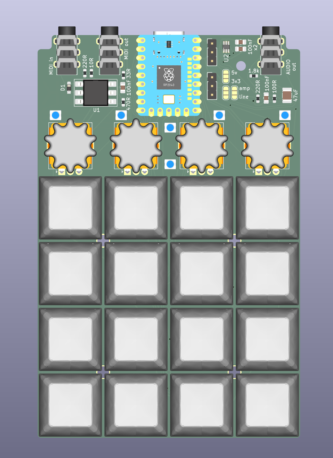
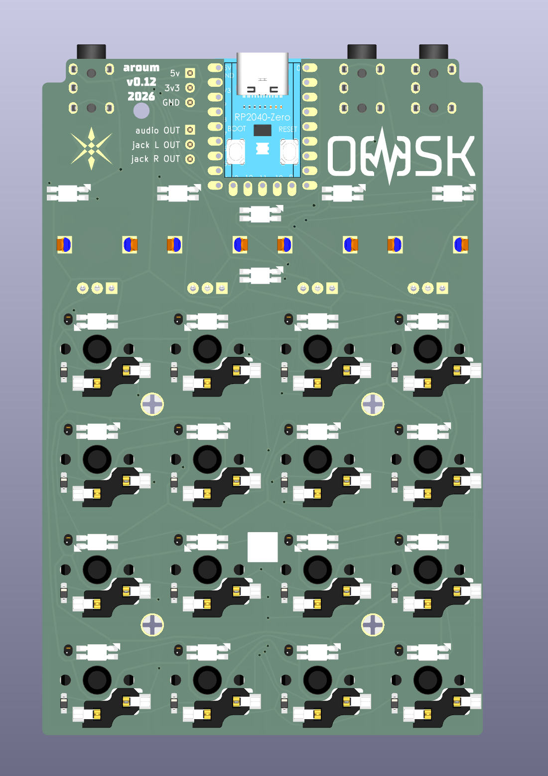
| name | pcs | type | package | position | description |
|---|---|---|---|---|---|
| 1N4148W | 17 | Diode | SOD-323 | D1 - D17 | keyboard matrix + MIDI |
| 100nF x7r 50v | 4 | Capacitor | 0805 | C1, C3, C4, C5 | MIDI jacks + PWM Audio |
| 47uF x7r 50v | 1 | Capacitor | 1210 | C2 | PWM audio |
| 10R for 3v3 or 220 Ohm for 5v out | 1 | Resistor | 0603 | R4 | MIDI jacks |
| 33R for 3v3 or 220 Ohm for 5v out | 1 | Resistor | 0603 | R3 | MIDI jacks |
| 100R | 1 | Resistor | 0603 | R6 | PWM audio |
| 220R | 2 | Resistor | 0603 | R1, R5 | PWM audio + MIDI jacks |
| 470R | 1 | Resistor | 0603 | R2 | MIDI jacks |
| 1.8k | 1 | Resistor | 0603 | R7 | PWM audio |
| PJ-313 (3 color) | 3 | jack sockets | THD | J2, J3, J4 | Audio + MIDI jacks |
| Alps EC12 8.5 mm | 4 | Encoder | THD | ROTENC1 - ROTENC4 | Encoder for more info view below |
| H11L1 SMD | 1 | Optocoupler | SOP-6 | U1 | MIDI jacks |
| Kailh choc sockets | 16 | Switch socket | SMD | SW1 - SW16 | keyboard |
| Kailh choc v2 | 16 | Switch | THD | SW1 - SW16 | keyboard |
| NC7WZ16P6X | 1 | IC | SC-70-6 | U2 | MIDI jacks + PWM audio |
| rp2040/rp2350 zero | 1 | MCU | Module | MCU1 | MCU (rp2350 recomended) |
| WS2812B MINI-E | 22 | RGB LED | 3228SMD | LED1 - LED22 | WS2812B MINI-E |
You can choose any one of the following encoder models:
| name | torque | # of detent/pulses | description |
|---|---|---|---|
| EC12E1220301 | Standard 3 to 20mN・m | 12 | |
| EC12E1240301 | Lightest (jog) 3±2mN・m | 12 | |
| EC12E2420301 | Standard 3 to 20mN・m | 24 | recommended |
| EC12E2440301 | Lightest (jog) 3±2mN・m | 24 | recommended |
| name | pcs | type | package | description |
|---|---|---|---|---|
| MIDI cable (DIN5 M to jack 3.5) | 1 | Cable | Cable | TRS to DIN5 MIDI cable (Type A) for use external MIDI hardware |
| YS-SK6812MINI-E | 22 | RGB LED | 3228SMD | RGB LEDs |
You can choose any one of the following display models:
| name | pcs | type | package | description |
|---|---|---|---|---|
| TZT 1.3" OLED 64×128 i2c SSD1312 | 1 | Display | Module | |
| TZT 1.3" OLED 64×128 i2c SH1107 | 1 | Display | Module | recommended |
| Module pin | MCU pin |
|---|---|
| GND | GND |
| VCC | 3.3V |
| SDA | GPIO20 |
| SCL | GPIO21 |
Formally, you should not connect headphones directly to the DAC or PWM output without an amplifier; however, in practice, it works fine directly, making an amplifier highly optional. If you decide to use one, you can choose any of the following headphone amplifier models:
| IC | mW | size | price | description |
|---|---|---|---|---|
| TPA6132 | 25 | S | 90 | |
| TDA1308 | 40-80 | S | 71 | |
| MAX4410 | 80 | M | 157 | |
| MAX97220 +++ | 125 | 20x24 | 225 | tested |
| OPA1622 | 145 | L | 113 | |
| LM4881 | 150 | M | 60 | |
| TPA6112 & SGM4812 | 150 | M | 183 |
GY-PCM5102 I2S PCM5102A module
| Module pin | MCU pin / Connection |
|---|---|
| GND | GND |
| VCC | 5V |
| BCK | GPIO17 |
| LRCK | GPIO18 |
| DIN | GPIO19 |
| SCK | GND (solder jumper next to SCK pin or wire to GND) |
LINE position (if you plan to use PWM audio).5V/3V3 jumper to the required position. This jumper controls the supply voltage of the NC7WZ16P6X (U2) IC. This affects the voltage of the MIDI OUT jack (for 5V, you must change resistors R3-R4 to 220 Ohm) and the PWM audio output level (5V increases the volume significantly, but might introduce noise from the USB power line).AMP positionAMP position| Qty | Value | Footprint | References |
|---|---|---|---|
| 22 | YS-SK6812MINI-E | mkl:LED_YS-SK6812MINI-E_1side | LED1, LED2, LED3, LED10, LED11, LED12, LED13, LED14, LED15, LED16, LED17, LED18, LED19, LED20, LED21, LED22 +6 |
| 17 | 1N4148W | mkl:D_SOD-323_1side | D1, D2, D3, D4, D5, D6, D7, D8, D10, D11, D12, D13, D14, D15, D16, D17 +1 |
| 16 | SW_PUSH | mkl:SW_choc12_hotswap | SW1, SW2, SW3, SW4, SW5, SW6, SW7, SW8, SW9, SW10, SW11, SW12, SW13, SW14, SW15, SW16 |
| 4 | 100nF | Capacitor_SMD:C_0805_2012Metric_Pad1.18x1.45mm_HandSolder | C1, C3, C4, C5 |
| 4 | MountingHole | didSwitch:mountingHole | H1, H2, H3, H4 |
| 4 | RotaryEncoder_Switch_MP | mkl:RotEnc_Alps_EC12E-SWitch_Vertical_H20mm-without_SW | RotEnc1, RotEnc2, RotEnc3, RotEnc4 |
| 3 | Jumper_3_Open | Jumper:SolderJumper-3_P1.3mm_Open_RoundedPad1.0x1.5mm | JP1, JP2, JP3 |
| 3 | PJ-313 | mkl:JACK_PJ-313A_1side | J2, J3, J4 |
| 2 | 220R | mkl:R_0603_1608Metric_1side | R1, R5 |
| 2 | Conn_01x03_Socket | Connector_PinHeader_2.54mm:PinHeader_1x03_P2.54mm_Vertical | J1, J5 |
| 2 | LOGO | LOGO | G1, G43 |
| 1 | 1.8k | mkl:R_0603_1608Metric_1side | R7 |
| 1 | 100R | mkl:R_0603_1608Metric_1side | R6 |
| 1 | 10R | mkl:R_0603_1608Metric_1side | R4 |
| 1 | 33R | mkl:R_0603_1608Metric_1side | R3 |
| 1 | 470R | mkl:R_0603_1608Metric_1side | R2 |
| 1 | 47uF | Capacitor_SMD:C_1210_3225Metric_Pad1.33x2.70mm_HandSolder | C2 |
| 1 | H11L1 | Package_DIP:DIP-6_W8.89mm_SMDSocket_LongPads | U1 |
| 1 | NC7WZ16P6X | mkl:SOT65P210X110-6N | U2 |
| 1 | rp2040-zero | mkl:MCU_rp2040-zero | MCU1 |
It measures 76.1 × 116.7 mm and has 2 copper layers, 1.6 mm thick.
88 parts, built around the NC7WZ16P6X, H11L1, 1N4148W and PJ-313. The full list of its parts is on this page, with links to each part's symbol and footprint where PCBKit's library has them.
From the aroum/omsk repository on GitHub, at the commit this page was made from: the board is hardware/pcb/omsk.kicad_pcb and its schematic hardware/pcb/ENC.kicad_sch. PCBKit opens the board in the browser, with nothing to install.
Its repository publishes it under the GPL-3.0 licence: you may reuse it on that licence's terms (keep the author's notice, and for a copyleft licence share your changes alike).


zephray/ELTerm
ANSI/VT100-compatible serial terminal built with Raspberry Pi Pico and EL640.480-AM/AG screen


EDA-bench/eda-bench
Execution-based benchmark for open-book KiCad PCB reconstruction agents

cwillforeal/cwill_keyboard
Test Repo For messing around with keyboard things and the pico

