
4 layers25.9 × 63.9 mm
Easyduino ESP32S3
Hanqaqa/Easyduino
Easily dive into different PCB KiCad designs of the most popular microcontroller devboards
35 parts755CERN-OHL-P-2.0
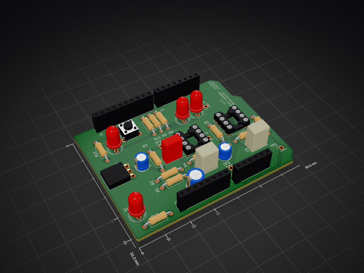
CW Doppler radar with on-chip CA-CFAR detection (PSoC5), custom PCB, and MATLAB verification
Lab SDHD is an open-source printed circuit board by Archit293, from the Archit293/Real-Time-Radar-Detection repository on GitHub. It is a 4-layer board of 68.6 × 53.3 mm with 35 parts on 45 nets, routed with 99 tracks and 1 via.
Its parts include 12 resistors, 6 capacitors, 5 connectors, 4 diodes and 2 ICs.
A continuous-wave (CW) Doppler radar system with on-chip target detection, built on a Cypress/Infineon PSoC5 microcontroller, with a custom PCB and a MATLAB testbench used to verify the embedded signal processing against a reference implementation.
The system samples an incoming analog signal, runs a real-time FFT on the microcontroller itself, and applies CA-CFAR (Cell-Averaging Constant False Alarm Rate) detection to automatically flag a moving target while keeping the false-alarm rate statistically controlled — a standard radar signal-processing technique, implemented here entirely in embedded C on a resource-constrained microcontroller. A MATLAB testbench then cross-checks the on-chip results against MATLAB's own FFT of the same raw data to confirm the embedded implementation is correct.
.
├── KiCad_Project/     # Custom PCB: schematic, layout, and fabrication (Gerber) files
├── PSoC_Project/      # PSoC5 firmware: ADC capture, FFT, CFAR detection
└── MATLAB_TestBench.m # Host-side verification: triggers a capture, compares FFTs Analog ADC Capture Windowing FFT CFAR
Input --> (1024 samples) --> (Hann) --> (1024-pt) --> Detection
|
v
UART (115200 baud)
|
v
MATLAB verification
(compares on-chip vs.
reference FFT)| Stage | Detail |
|---|---|
| Capture | 1024 samples via the PSoC's delta-sigma ADC |
| Windowing | Hann window applied in-place to reduce spectral leakage before the FFT |
| FFT | 1024-point FFT (CMSIS-DSP, fixed-point Q31) |
| Power spectrum | Magnitude computed from the real/imaginary FFT output pairs |
| CFAR detection | Cell-Averaging CFAR: NR=10 reference cells per side, NG=1 guard cell per side, target false-alarm probability PFA=1e-6 |
The firmware supports two modes:
KiCad_Project/ contains the full custom PCB design (schematic, board
layout, and the Gerber/drill files needed to send it to a fab house).
MATLAB_TestBench.m connects to the board over serial, triggers a capture
via a push-button handshake, and for each transfer:
This closes the loop on correctness: the same signal is processed two ways — once on the constrained embedded target, once on a full-precision reference — and the results are checked against each other directly.
PSoC_Project/Lab_SDHD_Radar.cywrk in PSoC Creator.
Peripheral drivers are regenerated automatically on build from the
schematic (TopDesign/TopDesign.cysch) and are not checked into this repo.KiCad_Project/Lab_SDHD.kicad_pro in KiCad.MATLAB_TestBench.m in MATLAB with the board
connected over USB (requires the serialport interface).| Qty | Value | Footprint | References |
|---|---|---|---|
| 4 | 330 | Resistor_THT:R_Axial_DIN0207_L6.3mm_D2.5mm_P10.16mm_Horizontal | R8, R9, R10, R11 |
| 2 | 1k | Resistor_THT:R_Axial_DIN0207_L6.3mm_D2.5mm_P10.16mm_Horizontal | R1, R2 |
| 2 | 4.7u | Capacitor_THT:CP_Radial_D5.0mm_P2.00mm | C1, C5 |
| 2 | OPA340P | Package_DIP:DIP-8_W7.62mm_Socket | U1, U2 |
| 1 | 1.5n | Capacitor_THT:C_Rect_L7.2mm_W5.0mm_P5.00mm | C3 |
| 1 | 100 | Resistor_THT:R_Axial_DIN0207_L6.3mm_D2.5mm_P10.16mm_Horizontal | R7 |
| 1 | 100k | Resistor_THT:R_Axial_DIN0207_L6.3mm_D2.5mm_P10.16mm_Horizontal | R6 |
| 1 | 100nF | Capacitor_THT:C_Rect_L7.0mm_W3.5mm_P5.00mm | C4 |
| 1 | 10k | Resistor_THT:R_Axial_DIN0207_L6.3mm_D2.5mm_P10.16mm_Horizontal | R12 |
| 1 | 2.2k | Resistor_THT:R_Axial_DIN0207_L6.3mm_D2.5mm_P10.16mm_Horizontal | R3 |
| 1 | 220k | Resistor_THT:R_Axial_DIN0207_L6.3mm_D2.5mm_P10.16mm_Horizontal | R4 |
| 1 | 22u | Capacitor_THT:CP_Radial_D6.3mm_P2.50mm | C2 |
| 1 | 3.3n | Capacitor_THT:C_Rect_L7.2mm_W5.0mm_P5.00mm | C6 |
| 1 | 33k | Resistor_THT:R_Axial_DIN0207_L6.3mm_D2.5mm_P10.16mm_Horizontal | R5 |
| 1 | Analog | Connector_PinSocket_2.54mm:PinSocket_1x06_P2.54mm_Vertical | J3 |
| 1 | Conn_01x03_Pin | Connector_PinSocket_2.54mm:PinSocket_1x03_P2.54mm_Horizontal | J5 |
| 1 | Digital/PWM | Connector_PinSocket_2.54mm:PinSocket_1x08_P2.54mm_Vertical | J4 |
| 1 | Digital/PWM | Connector_PinSocket_2.54mm:PinSocket_1x10_P2.54mm_Vertical | J2 |
| 1 | LED | LED_THT:LED_D5.0mm | D4 |
| 1 | LED_G | LED_THT:LED_D5.0mm | D1 |
| 1 | LED_R | LED_THT:LED_D5.0mm | D3 |
| 1 | LED_Y | LED_THT:LED_D5.0mm | D2 |
| 1 | Power | Connector_PinSocket_2.54mm:PinSocket_1x08_P2.54mm_Vertical | J1 |
| 1 | PushButton | Button_Switch_THT:SW_PUSH_6mm_H5mm | SW1 |
| 1 | TP_IN | Connector_PinHeader_2.54mm:PinHeader_1x01_P2.54mm_Vertical | TP2 |
| 1 | TP_Op1 | Connector_PinHeader_2.54mm:PinHeader_1x01_P2.54mm_Vertical | TP4 |
| 1 | TP_PB | Connector_PinHeader_2.54mm:PinHeader_1x01_P2.54mm_Vertical | TP1 |
| 1 | TP_Vcm | Connector_PinHeader_2.54mm:PinHeader_1x01_P2.54mm_Vertical | TP3 |
| 1 | TP_Vout | Connector_PinHeader_2.54mm:PinHeader_1x01_P2.54mm_Vertical | TP5 |
Hanqaqa/Easyduino
Easily dive into different PCB KiCad designs of the most popular microcontroller devboards


Alia5/PiCCANTE
PiCCANTE is a powerful tool for exploring and reversing CAN busses of vehicles, based on Raspberry Pi Pico (any model)


Sgw32/KungFuSID
Kung Fu SID is a firmware based on Kung Fu Flash which allows SID emulation
It measures 68.6 × 53.3 mm and has 4 copper layers, 1.6 mm thick.
35 parts. The full list of its parts is on this page, with links to each part's symbol and footprint where PCBKit's library has them.
From the Archit293/Real-Time-Radar-Detection repository on GitHub, at the commit this page was made from: the board is KiCad_Project/Lab_SDHD.kicad_pcb and its schematic KiCad_Project/Lab_SDHD.kicad_sch. PCBKit opens the board in the browser, with nothing to install.
Its repository states no licence, so its author keeps all rights: ask Archit293 before reusing the design.