
2 layers96.6 × 82.8 mm

 AP-123456789/Starbie
Starbie is a custom embedded electronics project built around the Seeed Studio XIAO ESP32-C3 (RISC-V). It combines a Seeed XIAO ESP32-C3, a DHT11 temperature and humidity sensor, an MPU6050 IMU, a 0.96-inch I2C OLED…
Startbie is an open-source printed circuit board by AP-123456789, from the AP-123456789/Starbie repository on GitHub. It is a 2-layer board of 76.5 × 71 mm with 7 parts on 29 nets, routed with 68 tracks and 5 vias.
It is built around the DHT11. Its parts include 2 ICs, 2 connectors, 2 switches and 1 resistor. It belongs with the ESP32 and RISC-V boards of this library.
Starbie is a custom embedded electronics project built around the Seeed Studio XIAO ESP32-C3 (RISC-V). It combines a Seeed XIAO ESP32-C3, a DHT11 temperature and humidity sensor, an MPU6050 IMU, a 0.96-inch I2C OLED display, and two push buttons on a custom two-layer PCB designed from scratch in KiCad.
starbie/
├── Firmware/
│   ├── include/
│   ├── lib/
│   ├── src/
│   │   └── main.cpp          # Core C++ firmware
│   └── platformio.ini        # PlatformIO build configuration
├── Hardware/
│   ├── startbie.kicad_sch    # Schematic capture file
│   ├── startbie.kicad_pcb    # PCB layout file
│   ├── startbie.kicad_pro    # KiCad project file
│   └── Gerbers/              # Manufacturing files
└── README.mdThe firmware is written in C++ using the Arduino framework via PlatformIO in VS Code. It handles I2C communication with the OLED display while polling the push buttons and reading sensor data.
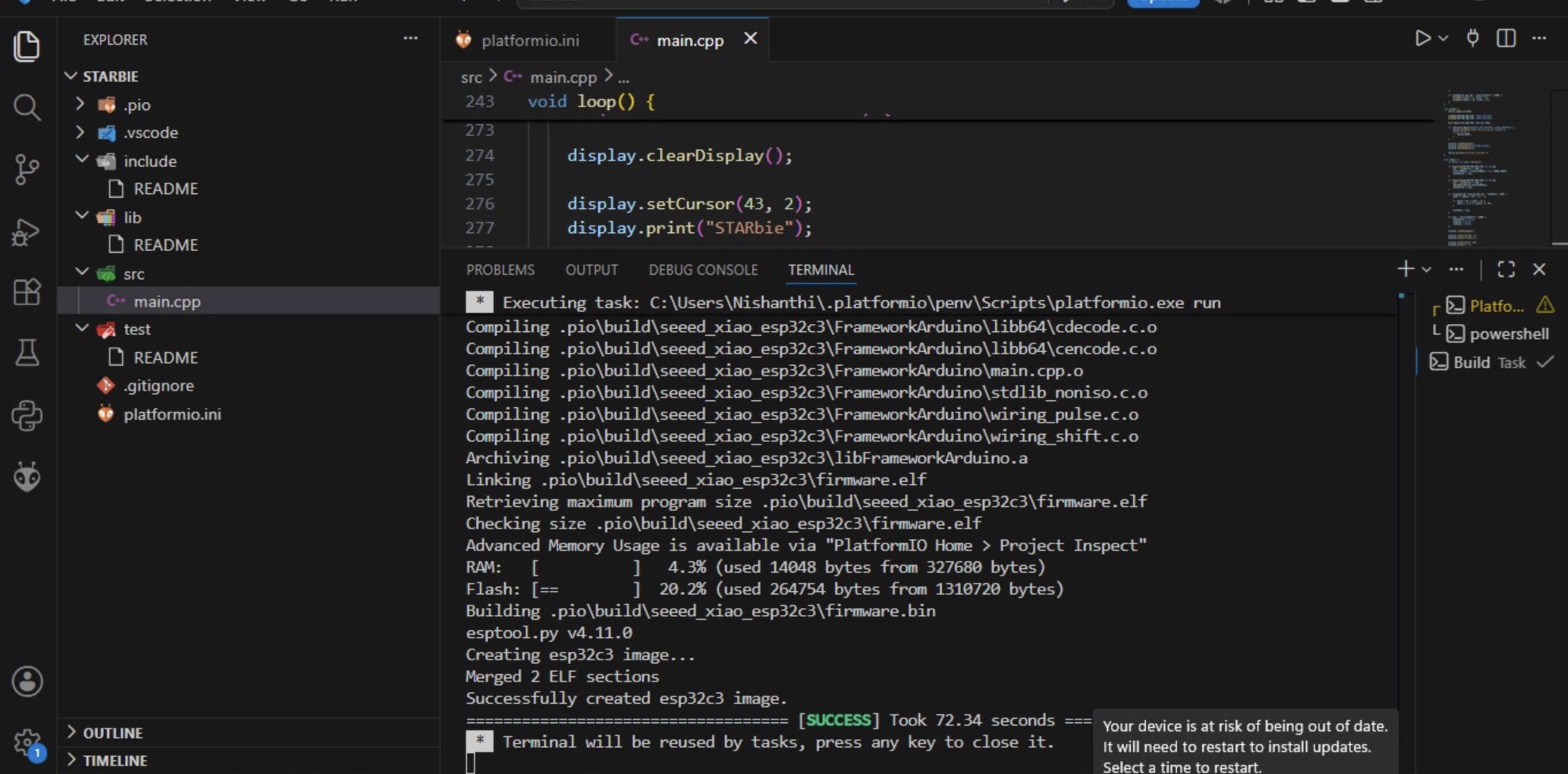
I started by setting up a PlatformIO workspace for the ESP32-C3, referencing the Seeed Studio XIAO ESP32-C3 Wiki. Right away, the build crashed with Error 10013: An attempt was made to access a socket in a way forbidden by its access permissions.
After trying admin mode and checking firewalls with having no success, I looked through PlatformIO Community Forum Discussions and GitHub Issues and realized local network security was blocking the registry port. Changing the package mirror source and clearing the local cache fixed the socket block and let dependencies download.
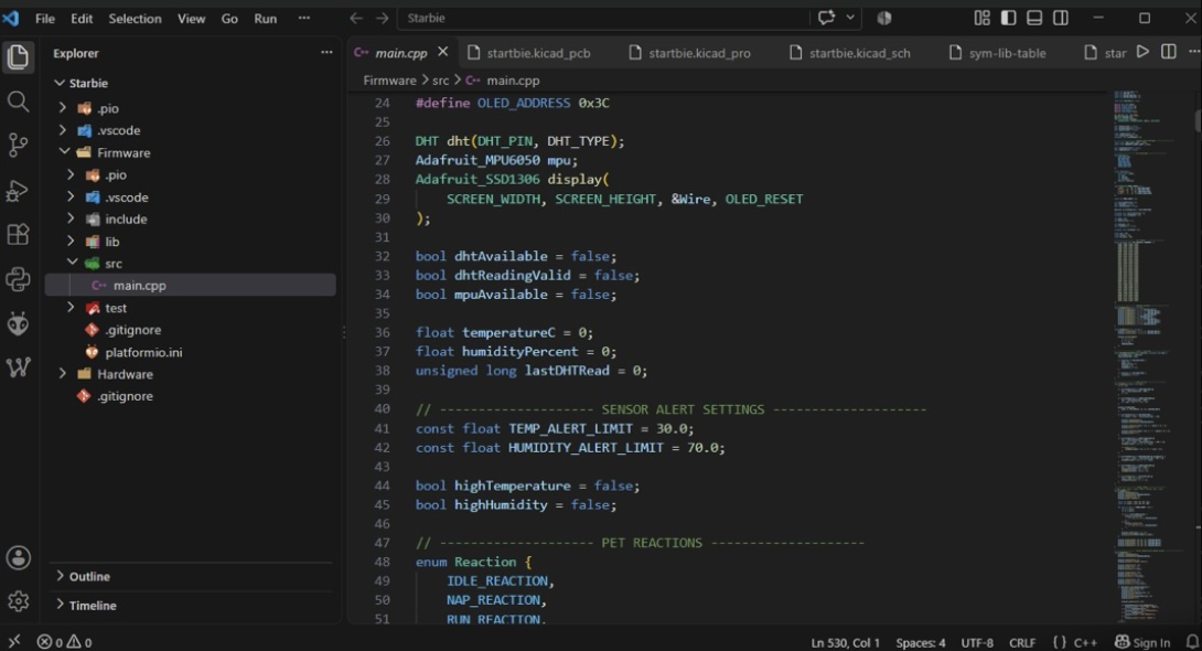
I wrote the core application logic in Firmware/src/main.cpp, integrating the Adafruit SSD1306 Library and Adafruit GFX Library. Compiling for the RISC-V architecture taught me a lot about managing memory and library conflicts before successfully generating the binary image, which I initially did not understand.
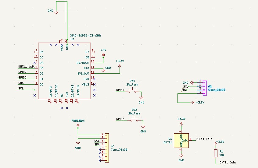
Transitioning to the hardware, I opened KiCad (startbie.kicad_sch) and placed the XIAO ESP32-C3 (U2), DHT11 (U1), push buttons (SW1, SW2), pin headers (J1, J2), and the $10\text{ k}\Omega$ pull-up resistor (R1) based on the DHT11 Datasheet.
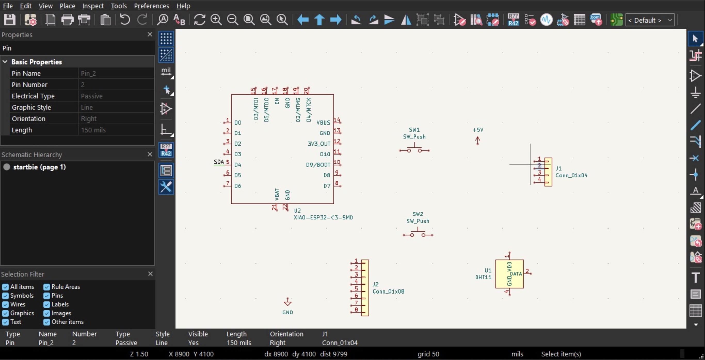
I learned why pull-up resistors are needed for digital single-wire data lines and how power flags (+3.3V, +5V, GND) work.
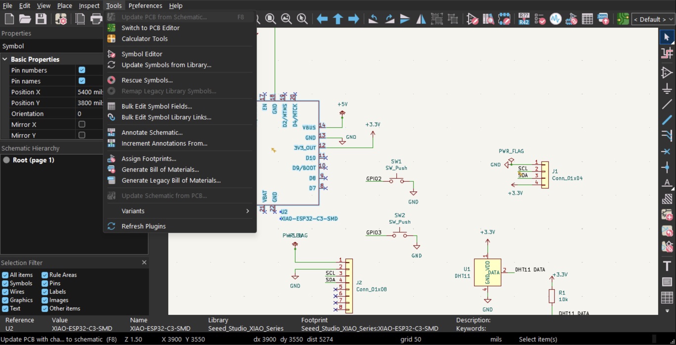
Running the Electrical Rules Checker (ERC) helped catch floating pins before moving to the board layout.
Updating the PCB layout from the schematic (referencing the KiCad Getting Started Guide) threw missing-footprint errors because default symbols weren't bound to physical packages.
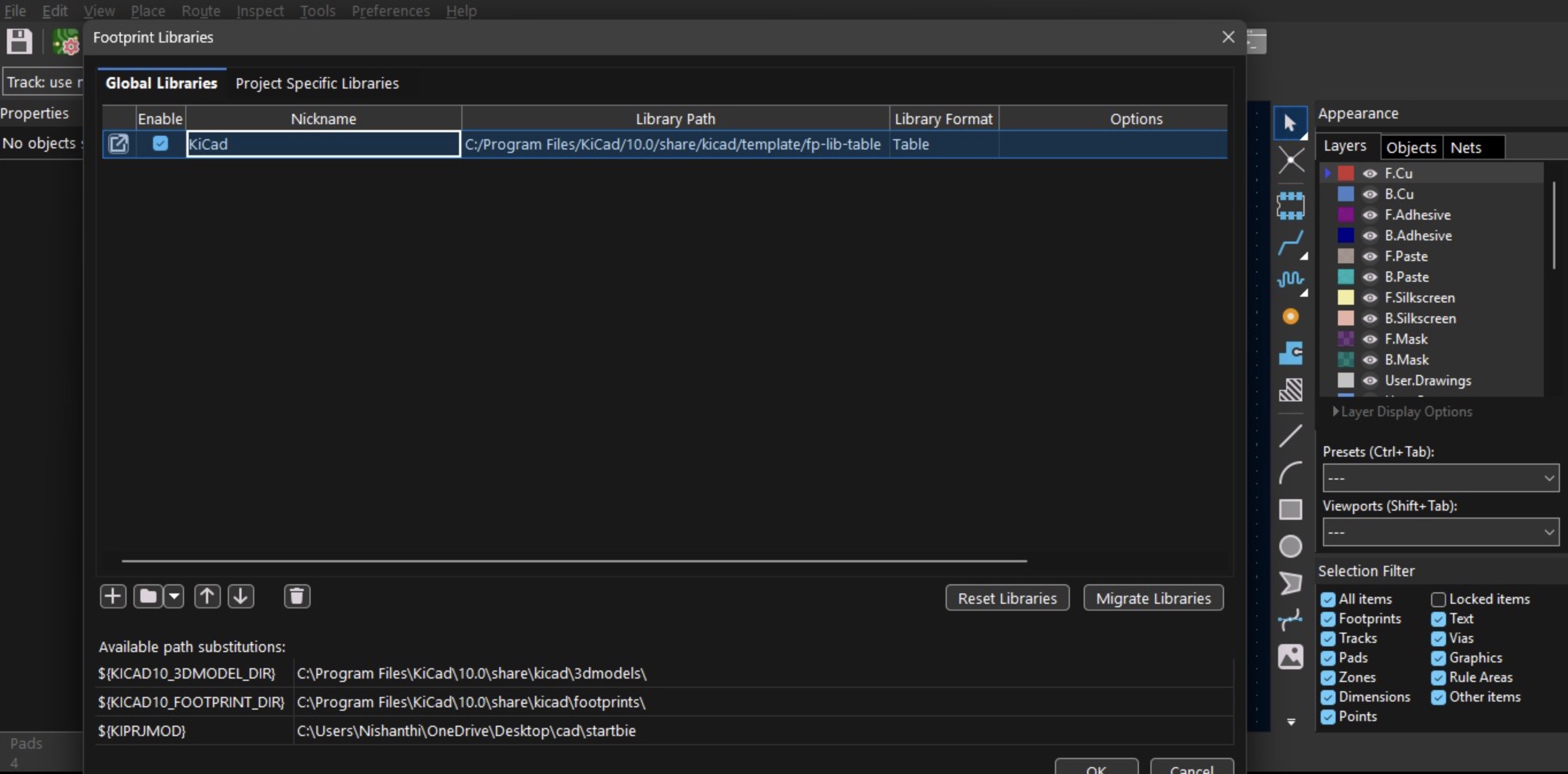
I used the Assign Footprints tool to map symbols to their exact physical packages.
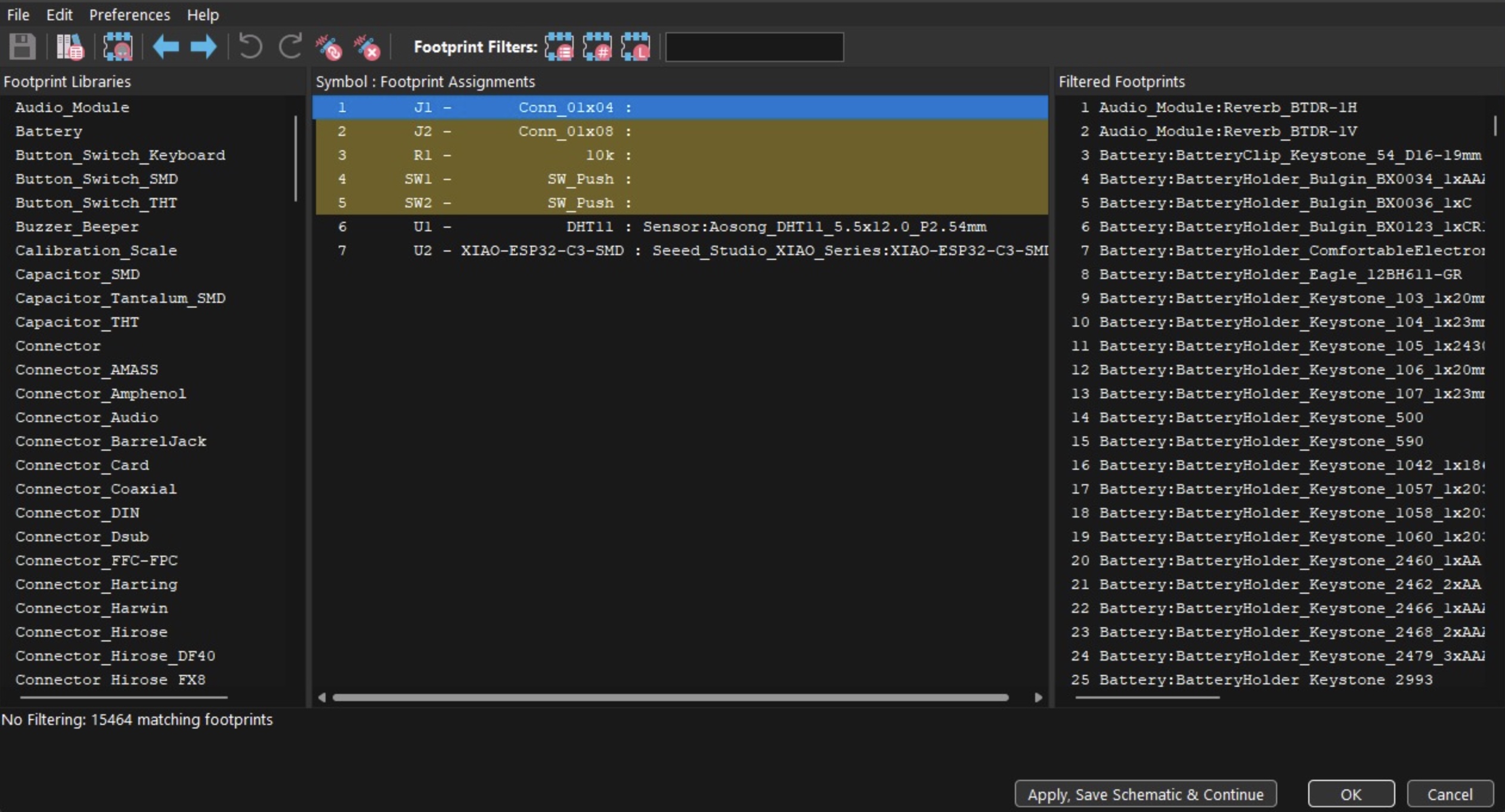
I hit a few search misses at first...
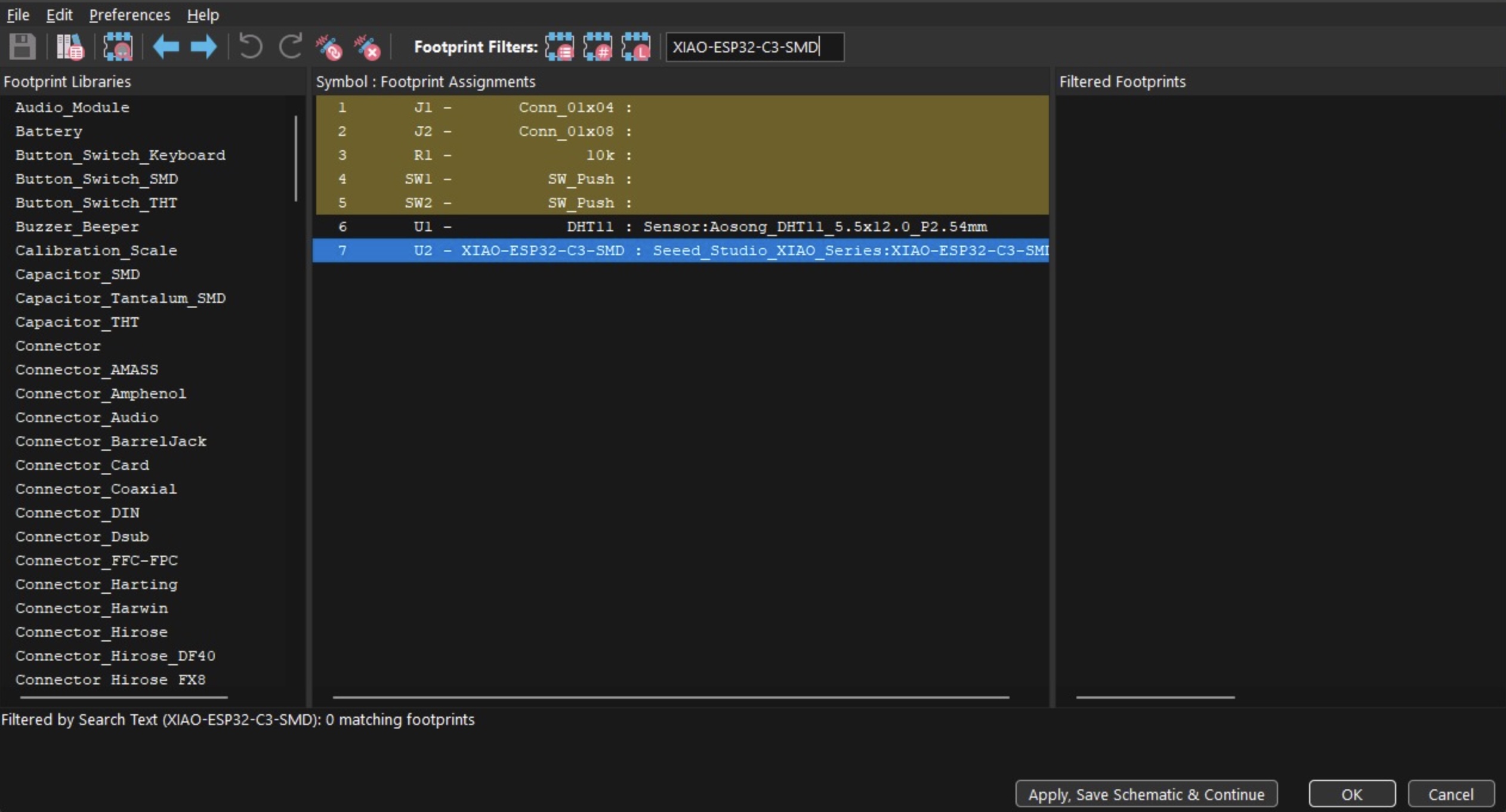
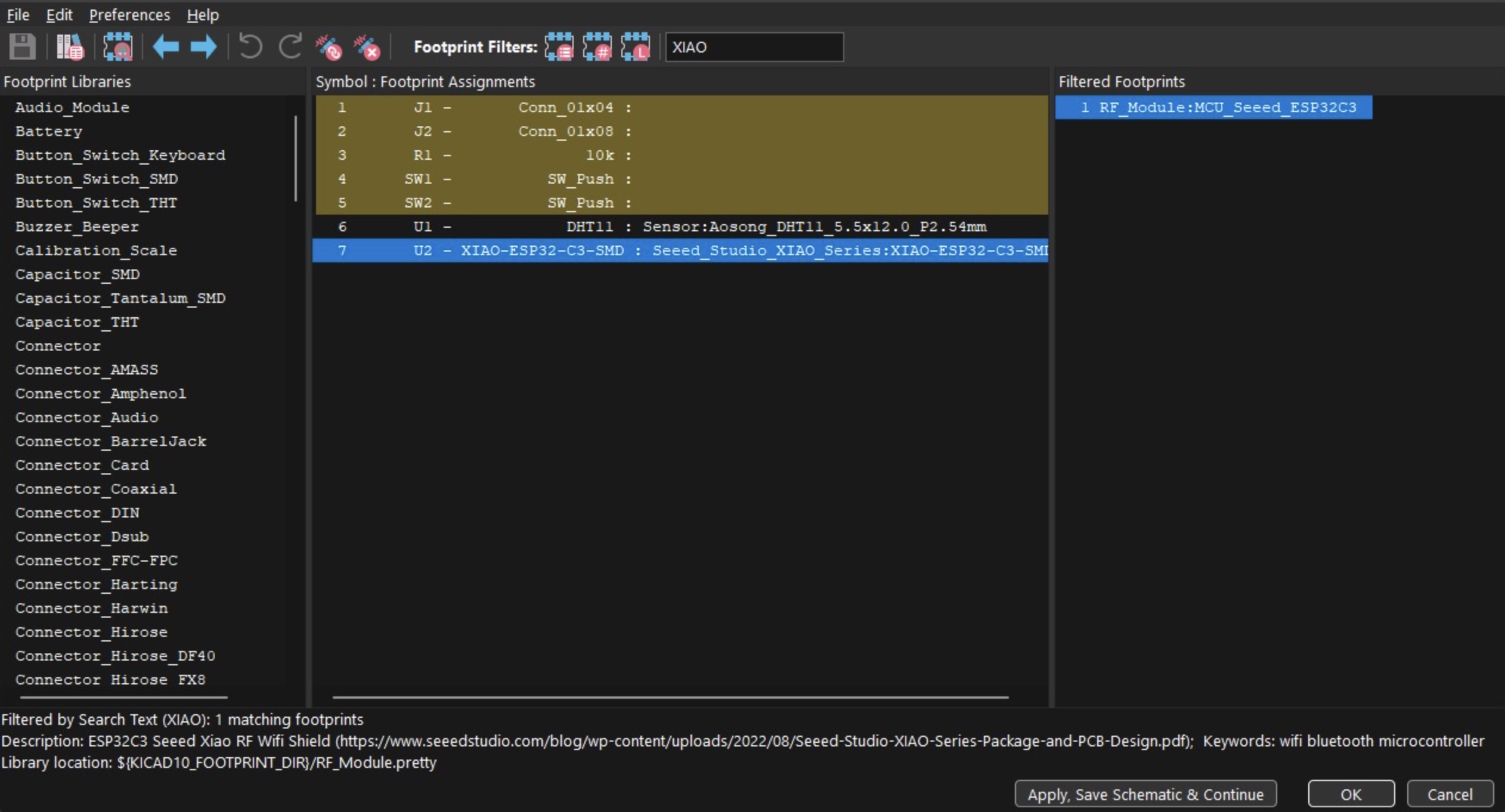
...but after fixing library paths, I found the correct packages (Sensor:Aosong_DHT11 and Seeed_Studio_XIAO_Series:XIAO-ESP32-C3-SMD).
Then I initialized the PCB canvas in startbie.kicad_pcb...
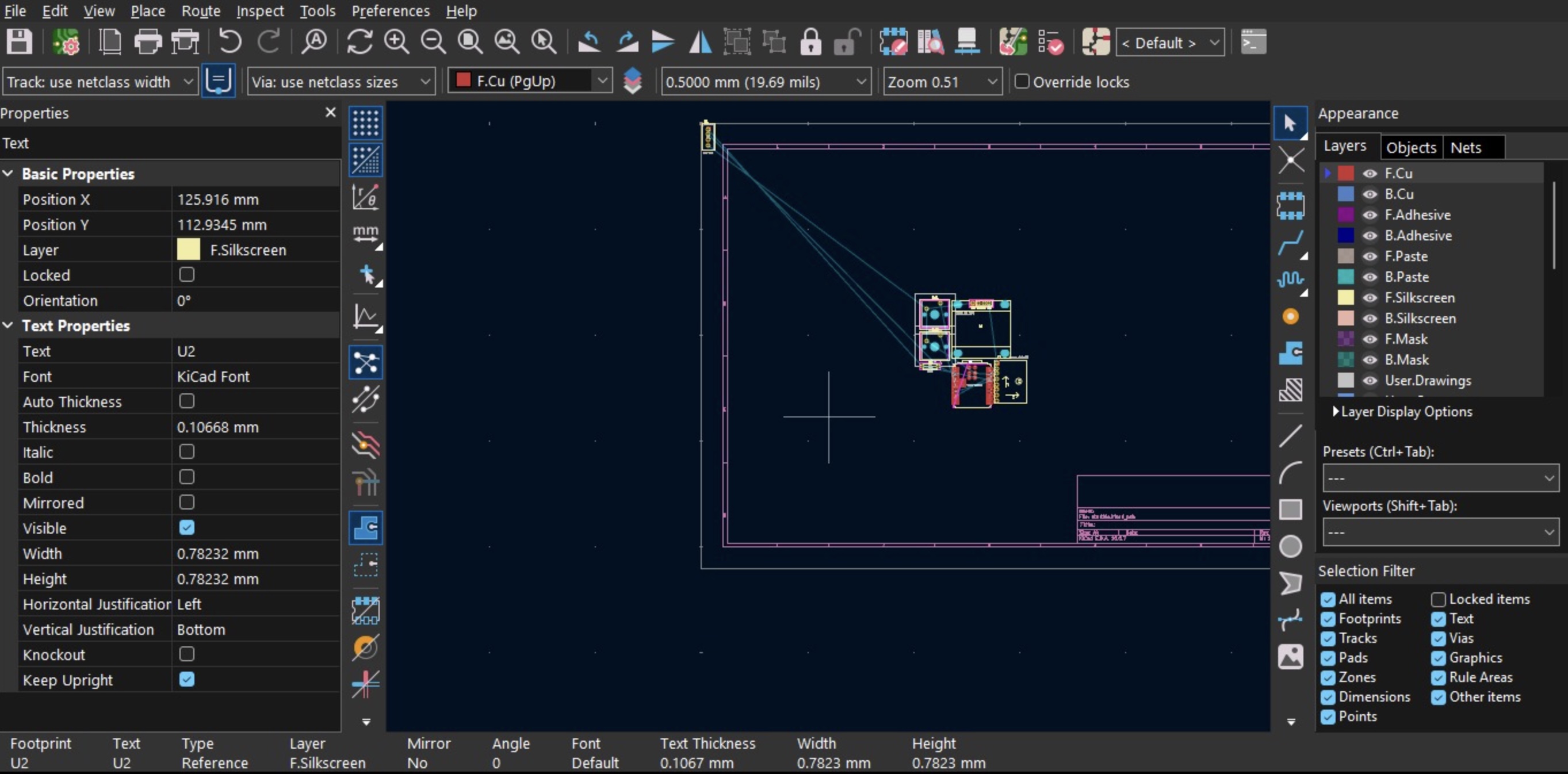
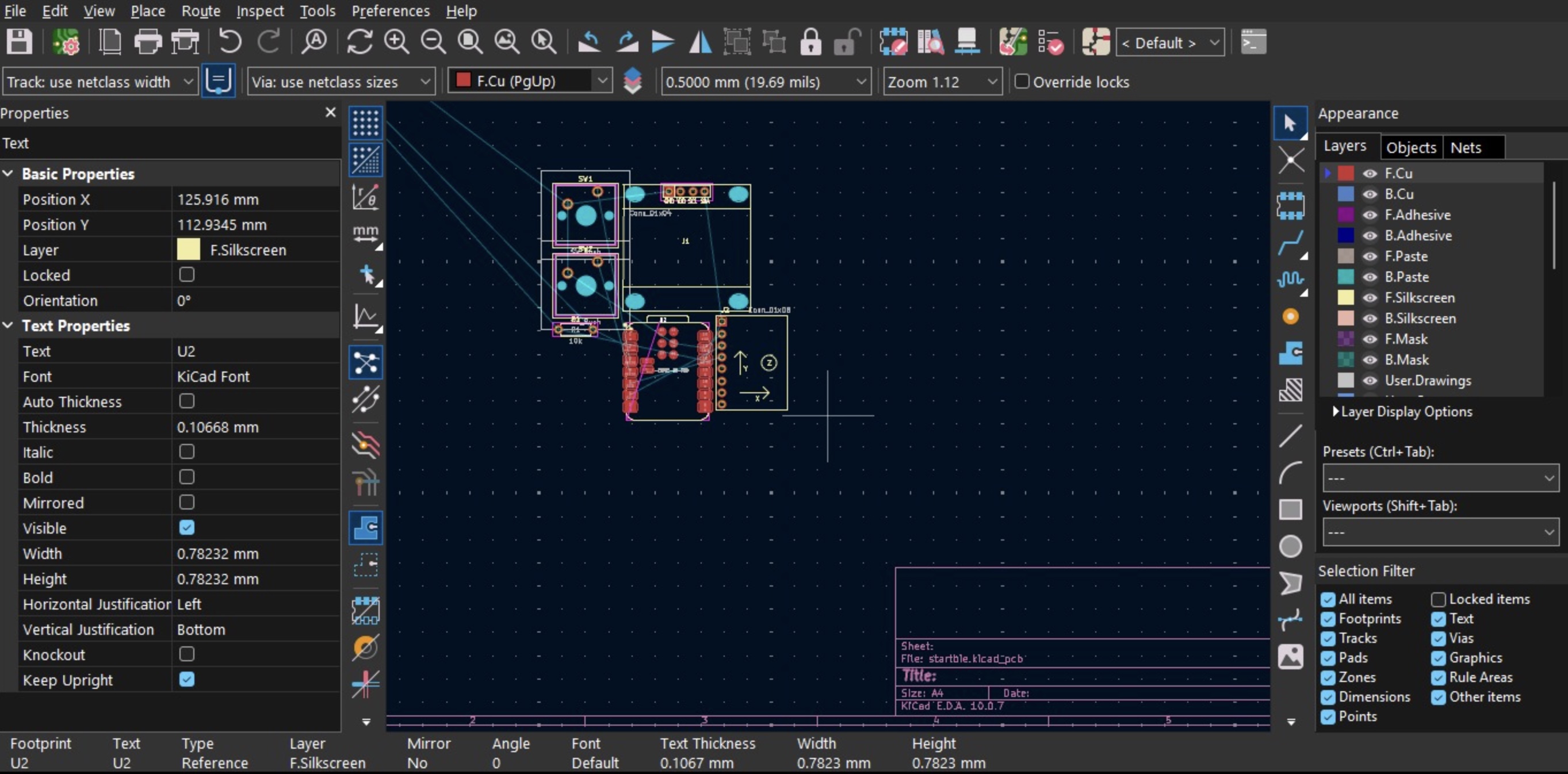
...placed the components...
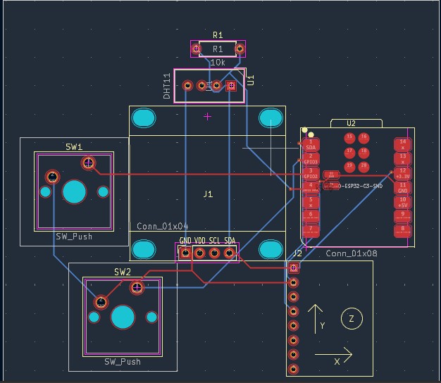
...and routed the copper traces on the top (F.Cu, red) and bottom (B.Cu, blue) layers.
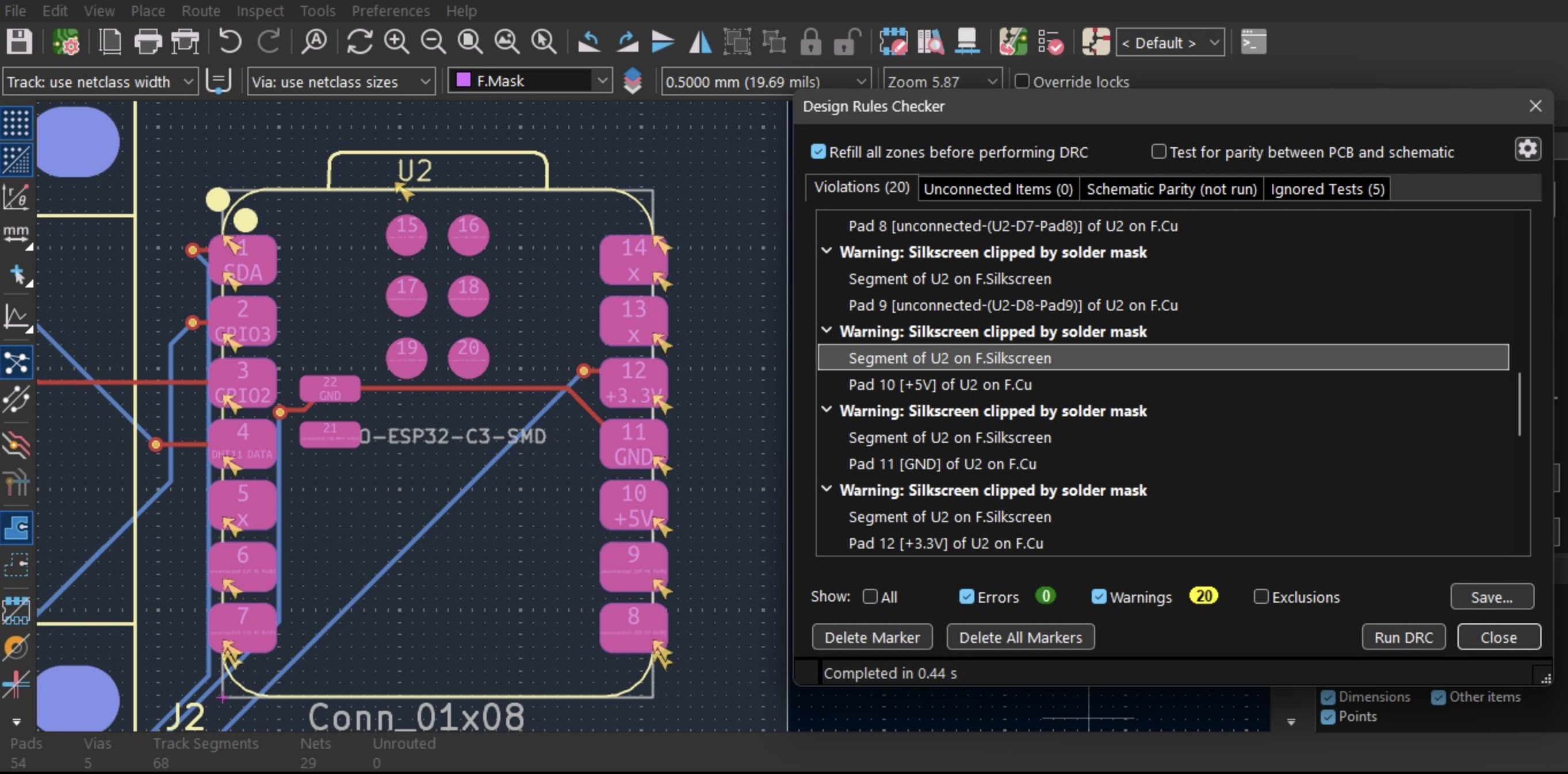
When I ran the Design Rules Checker (DRC), it flagged 5 errors and 20 warnings.
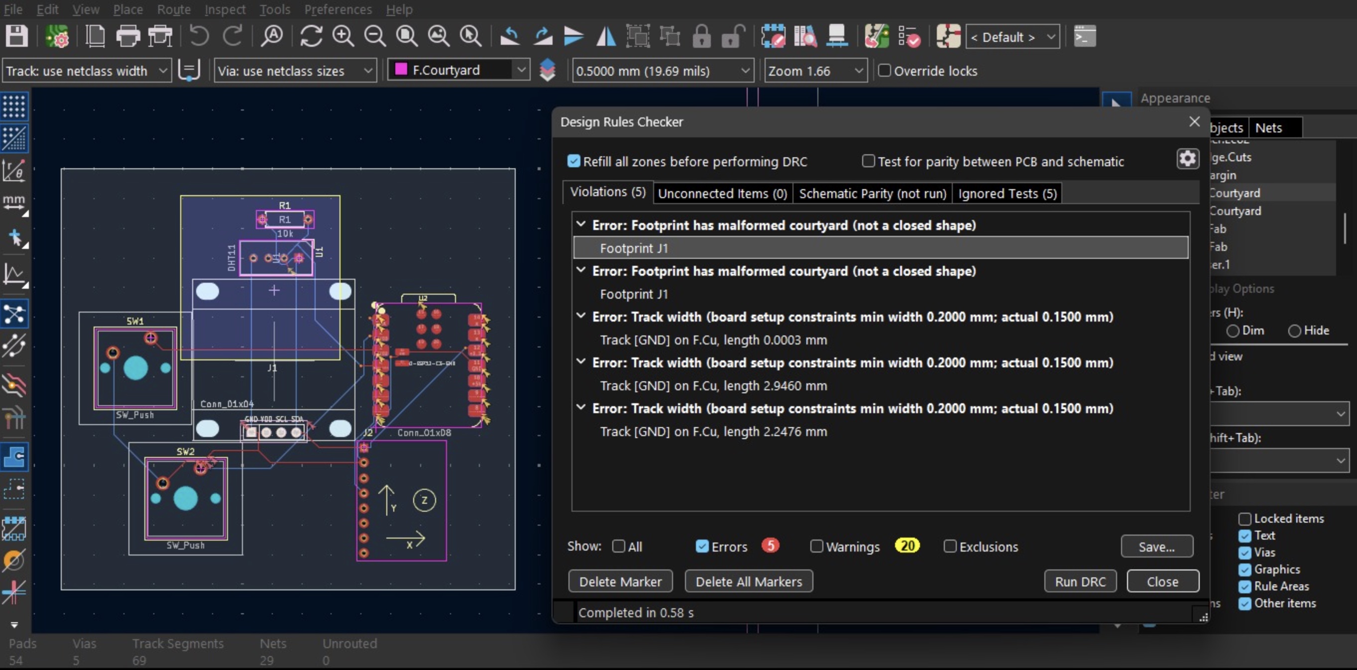
I had to fix courtyard errors, widen traces that were under $0.2000\text{ mm}$, and clear silkscreen text overlapping solder masks.
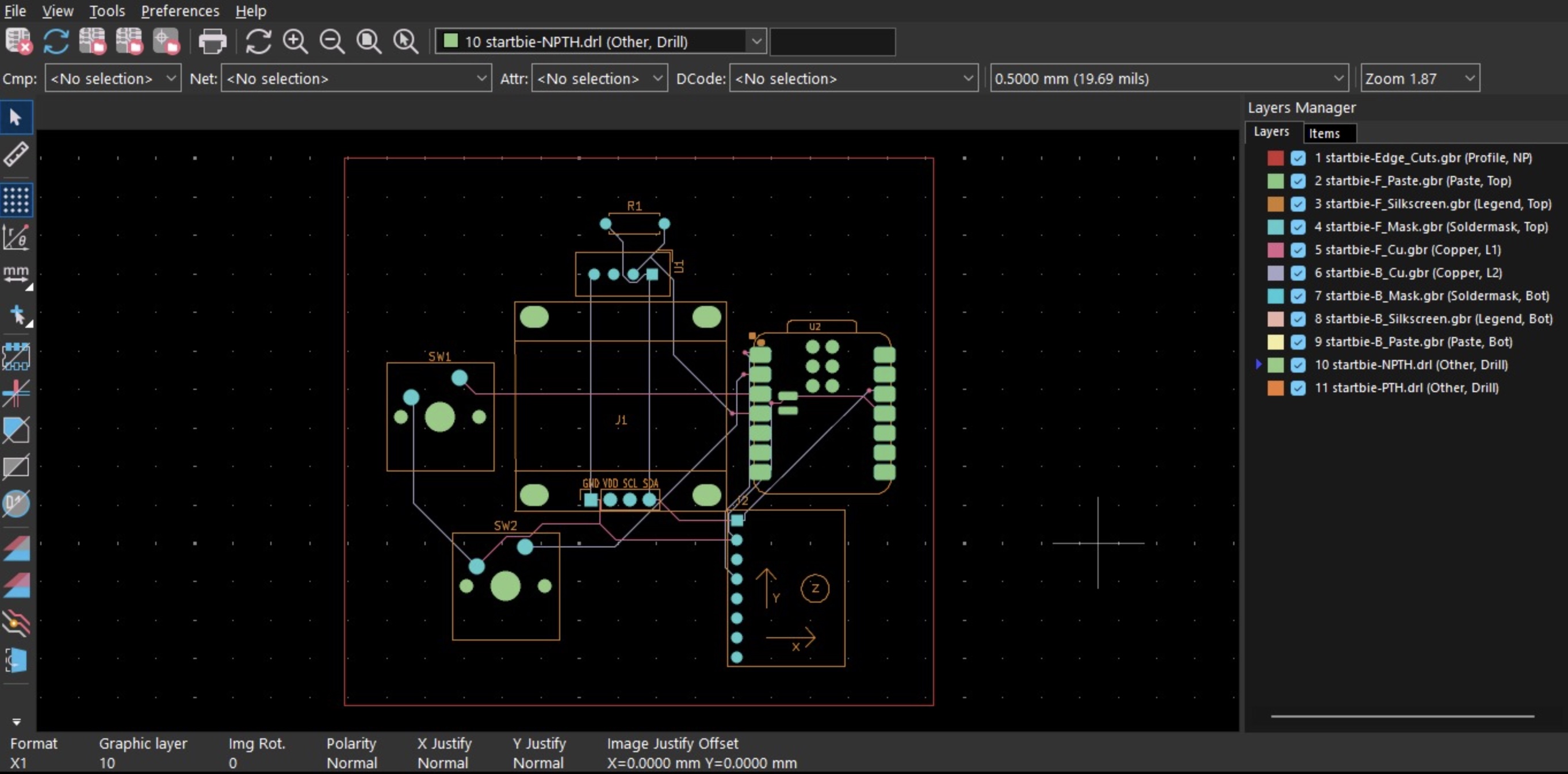
With a clean DRC check, I generated manufacturing files and inspected them in the KiCad Gerber Viewer.
Finally, I added a .gitignore, initialized git, and pushed the repo to GitHub.
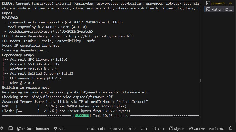
I updated the Starbie firmware by adding a temperature and humidity alert system using the DHT11 sensor. The system monitors temperature and humidity and triggers warnings when the temperature exceeds 30°C or humidity exceeds 70%. I also updated the OLED Stats screen to display the sensor readings and corresponding warning messages. If both values exceed their limits, the display indicates both alerts; if the sensor readings are unavailable, it shows “Climate unavailable.” The updated firmware compiled successfully in PlatformIO, confirming that there were no compilation errors.
| REFERENCE | VALUE | QUANTITY | DESCRIPTION |
|---|---|---|---|
| U2 | XIAO ESP32-C3 | 1 | Main microcontroller |
| U1 | DHT11 | 1 | Temperature and humidity sensor |
| SW1 | Push Button | 1 | User input button |
| SW2 | Push Button | 1 | User input button |
| R1 | 10k Ohm | 1 | Resistor |
| J1 | 4-pin connector | 1 | Power and I²C connections |
| J2 | 8-pin connector | 1 | Component connections |
| Qty | Value | Footprint | References |
|---|---|---|---|
| 2 | SW_Push | Button_Switch_Keyboard:SW_Cherry_MX_1.00u_PCB | SW1, SW2 |
| 1 | 10k | Resistor_THT:R_Axial_DIN0207_L6.3mm_D2.5mm_P7.62mm_Horizontal | R1 |
| 1 | Conn_01x04 | Imported Parts:Display_128x64_096_I2C | J1 |
| 1 | Conn_01x08 | Imported Parts:MPU6050_Module | J2 |
| 1 | DHT11 | Sensor:Aosong_DHT11_5.5x12.0_P2.54mm | U1 |
| 1 | XIAO-ESP32-C3-SMD | Imported Parts:XIAO-ESP32-C3-SMD | U2 |

lansidev/conveyor-belt
Miniature 3D printed conveyor belt for simulation and fun working with sensors, all controllable with Raspberry Pi


ebrithiljonas/OMG_PCB
All in One PCB for the OpenMQTTGateway Project

GeorgK/SniffingTrinket
A room climate monitor using the Adafruit Trinket Pro

bhaskar9980/Guardian
Guardian is an advanced, fully automated hydroponics system designed to optimize plant growth and maximize yield.

Twistx77/Firefly
Open WIFI-enabled RGB lamp with temperature, humidity, suspended air particles and eCO2 sensors.

unla-investigacion-desarrollo/ecosistema-iot
Antes de desarrollar el sistema final, realizamos una etapa de exploración donde investigamos y experimentamos con las siguientes tecnologías:
It measures 76.5 × 71 mm and has 2 copper layers, 1.6 mm thick.
7 parts, built around the DHT11. The full list of its parts is on this page, with links to each part's symbol and footprint where PCBKit's library has them.
From the AP-123456789/Starbie repository on GitHub, at the commit this page was made from: the board is Hardware/startbie.kicad_pcb and its schematic Hardware/startbie.kicad_sch. PCBKit opens the board in the browser, with nothing to install.
Its repository states no licence, so its author keeps all rights: ask AP-123456789 before reusing the design.