2 layers60 × 30 mm
Controller
google/mozc-devices
Circuit diagrams and firmware source code for Gboard DIY keyboards
11 parts3kApache-2.0

 aoishik/Advanced_Human_Detector1
This is a human detector which uses Mmwave Sensor to detect humans.
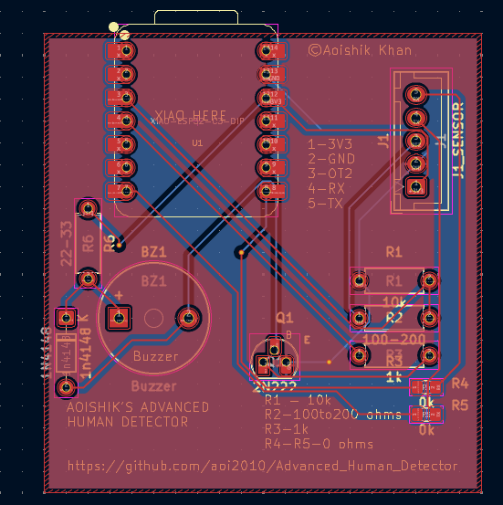
Motionalr mcu is an open-source printed circuit board by aoishik, from the aoishik/Advanced_Human_Detector repository on GitHub. It is a 2-layer board of 47.6 × 50 mm with 11 parts on 28 nets, routed with 68 tracks and 3 vias.
Its parts include 6 resistors, 1 IC, 1 transistor and 1 connector. It belongs with the sensors and measurement boards and the ESP32 and RISC-V boards of this library.
This is a human detector which uses HmmD Mmwave Sensor to detect humans.
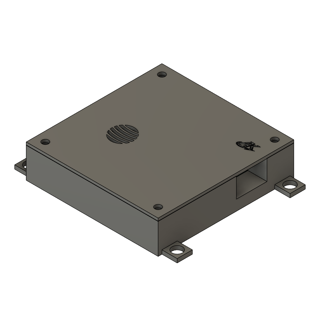
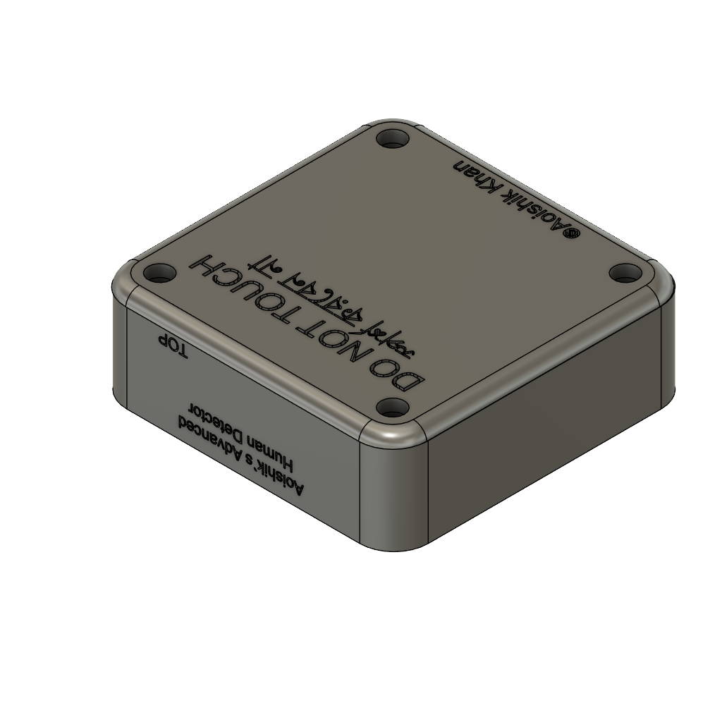
I wanted to create a human detector using the Mmwave Sensor to detect humans and alert me when human is detected cuz some people always steals the flowers in my garden, and I want to catch them in the act.
Believe it or not, this was my second time using Fusion 360 and KiCad! I watched numerous tutorials and guides and did a kg of googling, but in the end, I'm pretty proud of the final product. I had the most struggle figuring out how to make sketches, and with the new mouse controls, it definitely took me a while to get the hang of it. Also in KiCad, I had a lot of trouble with footprints and making sure everything was aligned properly and the traces were correct(but it became a litle long traces).
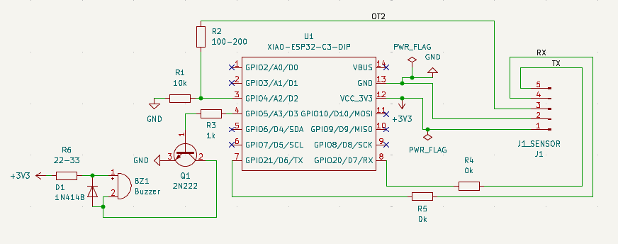
| Twisted Pair | Use For |
|---|---|
| Pair 1 | 3.3V + GND |
| Pair 2 | TX + GND |
| Pair 3 | RX + GND |
| Pair 4 | OT2 + GND |
BOM:
Others:
| Schematic | PCB | Sensor Case (Top) | Sensor Case (Bottom) |
|---|---|---|---|
 |  | 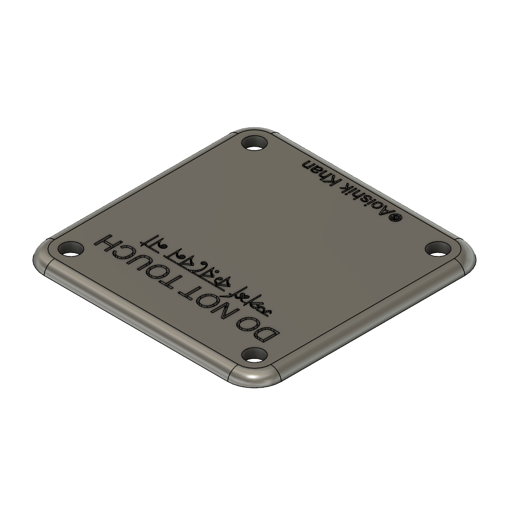 | 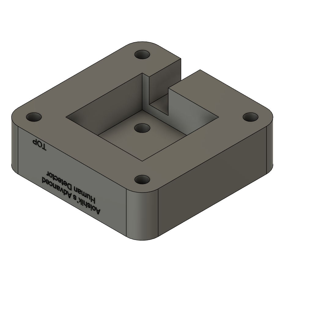 |
| PCB Case (Top) | PCB Case (Bottom) |
|---|---|
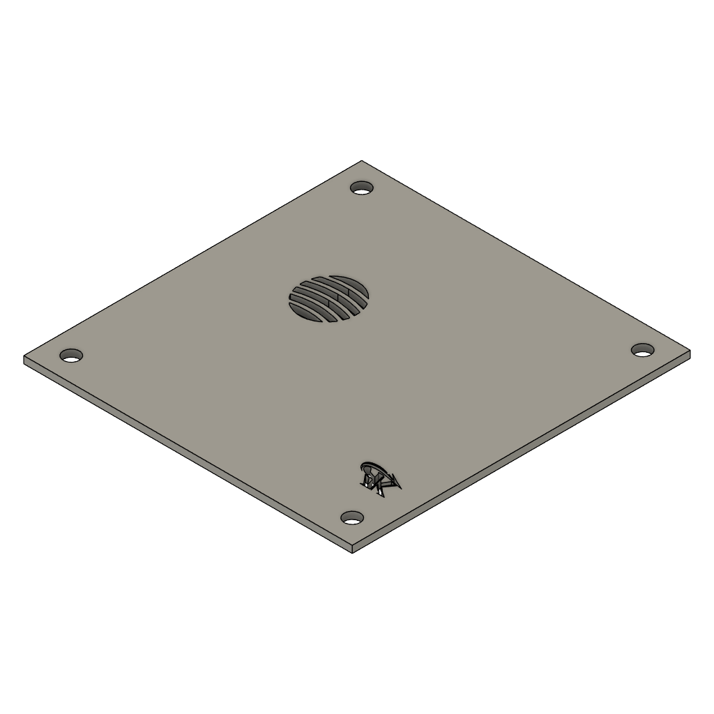 | 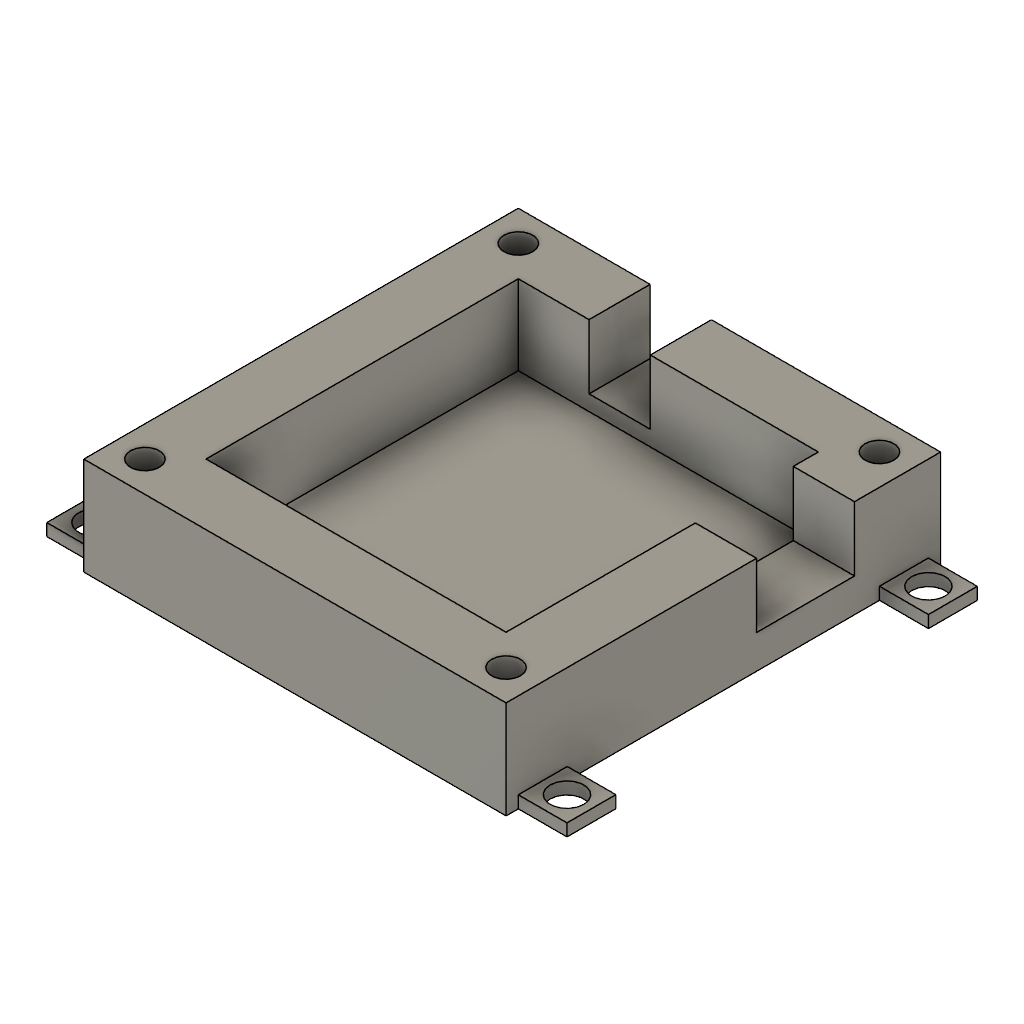 |
The code is still basic in functionality because of lack of information on the sensor datasheet, but I will update it as soon as I get the sensor and debug it's output. The case for the mmwave sensor is measured with approx measurement available online, so I will also update the case design once I get the sensor and measure it myself. The PCB will be left bare as I like looking at PCBs.
Edit: I also made the PCB case but after my project was approved. Thank You for understanding.
| Qty | Value | Footprint | References |
|---|---|---|---|
| 2 | 0k | Resistor_SMD:R_0805_2012Metric_Pad1.20x1.40mm_HandSolder | R4, R5 |
| 1 | 100-200 | Resistor_THT:R_Axial_DIN0207_L6.3mm_D2.5mm_P7.62mm_Horizontal | R2 |
| 1 | 10k | Resistor_THT:R_Axial_DIN0207_L6.3mm_D2.5mm_P7.62mm_Horizontal | R1 |
| 1 | 1N4148 | Diode_THT:D_DO-35_SOD27_P7.62mm_Horizontal | 1n4148 |
| 1 | 1k | Resistor_THT:R_Axial_DIN0207_L6.3mm_D2.5mm_P7.62mm_Horizontal | R3 |
| 1 | 22-33 | Resistor_THT:R_Axial_DIN0207_L6.3mm_D2.5mm_P7.62mm_Horizontal | R6 |
| 1 | 2N222 | Package_TO_SOT_THT:TO-92_HandSolder | Q1 |
| 1 | Buzzer | Buzzer_Beeper:Buzzer_12x9.5RM7.6 | BZ1 |
| 1 | J1_SENSOR | Connector_JST:JST_XH_B5B-XH-A_1x05_P2.50mm_Vertical | J1 |
| 1 | XIAO-ESP32-C3-DIP | OPL_XIAO:XIAO-ESP32C3-DIP | U1 |
google/mozc-devices
Circuit diagrams and firmware source code for Gboard DIY keyboards


FrameworkComputer/ExpansionCards
Reference designs and documentation to create Expansion Cards for the Framework Laptop

hoglet67/RGBtoHDMI
Bare-metal Raspberry Pi project that provides pixel-perfect sampling of Retro Computer RGB/YUV video and conversion to HDMI

hackclub/OnBoard
💡 Join 1,000 teenagers and make your first PCB with a $100 grant!


tardate/LittleArduinoProjects
a collection of "Little Electronic & Arduino Projects", most involving electronics or an Arduino in one way or another!

basilfx/TRADFRI-Hacking
Hacking IKEA TRÅDFRI products, such as light bulbs, window blinds and other accessories.
It measures 47.6 × 50 mm and has 2 copper layers, 1.6 mm thick.
11 parts. The full list of its parts is on this page, with links to each part's symbol and footprint where PCBKit's library has them.
From the aoishik/Advanced_Human_Detector repository on GitHub, at the commit this page was made from: the board is PCB/motionalr_mcu.kicad_pcb and its schematic PCB/motionalr_mcu.kicad_sch. PCBKit opens the board in the browser, with nothing to install.
Its repository states no licence, so its author keeps all rights: ask aoishik before reusing the design.