2 layers
Nrf bga
github-linguist/linguist
Language Savant. If your repository's language is being reported incorrectly, send us a pull request!
12 parts14kMIT

 anw6002/macropad
A custom Macropad designed for League of Legends gameplay
Macropad is an open-source printed circuit board by anw6002, from the anw6002/macropad repository on GitHub. It is a 2-layer board of 100 × 100 mm with 12 parts on 52 nets, routed with 51 tracks and 0 vias.
It belongs with the keyboards and input boards and the RP2040 boards of this library.
Table of Contents:
Overview · Hardware Design · PCB Specifications · Hardware Components
· GPIO Mapping · Technologies· Button Module Specifications
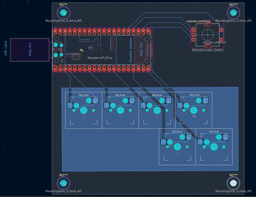
This project implements a custom USB macropad using the Raspberry Pi Pico. The macropad is designed for League of Legends, providing dedicated QWER ability keys, DF keys, and rotary encoder for volume controls. The firmware is written in C using the Raspberry Pi Pico SDK, and the final hardware is designed in KiCad and manufactured as a custom PCB.
There is a planned joystick expansion for character movement using League's new WASD support. Up to 20 additional keys will be included in the expansion.
The PCB is designed in KiCad for a Raspberry Pi Pico-based USB HID macropad (also compatible with the Raspberry Pi Pico 2). The board is intended to support six mechanical keyboard switches, with hot-swap sockets for easier switch replacement. The PCB will connect each key to a dedicated GPIO pin, with the switches sharing a common ground. The PCB design will accommodate a rotary encoder with push button for volume-control functionality.
| Component | Purpose |
|---|---|
| Raspberry Pi Pico | Microcontroller and USB HID interface |
| Kailh CPG151101S11 hot-swap sockets | Allow switches to be replaced without desoldering |
| MX Mechanical keyboard switches | Physical key inputs |
| Custom PCB | Mounts switches and microcontroller connections |
| Header pins / sockets | Connects the Pico to the PCB |
| 3D-printed enclosure | Houses and protects the assembled macropad |
| Rotary encoder | volume control knob |
| Key | Pico GPIO | Physical Pin |
|---|---|---|
| Q | GP01 | 02 |
| W | GP05 | 07 |
| E | GP09 | 12 |
| R | GP15 | 20 |
| D | GP13 | 17 |
| F | GP14 | 19 |
The switches use a shared ground connection, with GPIO internal pull-ups intended to be enabled in firmware.
The PCB is a work in progress. Footprint compatibility, electrical connections, clearances, and manufacturing outputs must be verified before fabrication.
The button module provides an interface for initializing and scanning the macropad's pushbuttons. It abstracts the GPIO hardware and
reports button press and release events.
This Macropad utilizes MX Mechanical Keyboard switches that connect the GPIO pin to GND when pressed.
When pressing a mechanical keyboard switch, metal contacts in the switch can briefly bounce, causing a short duration in which the microcontroller
reads a rapid fluctuation between HIGH (1) and LOW (0) for the pin. Debouncing is implemented to make sure a single button press does not register as multiple
events.
Software debouncing filters out these transient fluctuations by accepting a state change only after the button state has remained stable for a set amount of time, preventing
a single physical press from being registered as multiple events. For this repository's implementation, the debounce timer is set to 10 ms.
| Qty | Value | Footprint | References |
|---|---|---|---|
| 6 | SW_Push | MX_Hotswap:MX-Hotswap-1U | D1, E1, F1, Q1, R1, W1 |
| 1 | RaspberryPi_Pico | Module:RaspberryPi_Pico_Common_Unspecified | A1 |
| 1 | RotaryEncoder_Switch | Rotary_Encoder:RotaryEncoder_Alps_EC11E-Switch_Vertical_H20mm | volume_control1 |
The 8 most common of 12 parts.
It measures 100 × 100 mm and has 2 copper layers, 1.6 mm thick.
12 parts. The full list of its parts is on this page, with links to each part's symbol and footprint where PCBKit's library has them.
From the anw6002/macropad repository on GitHub, at the commit this page was made from: the board is hardware/macropad/macropad.kicad_pcb and its schematic hardware/macropad/macropad.kicad_sch. PCBKit opens the board in the browser, with nothing to install.
Its repository states no licence, so its author keeps all rights: ask anw6002 before reusing the design.
github-linguist/linguist
Language Savant. If your repository's language is being reported incorrectly, send us a pull request!


google/mozc-devices
Circuit diagrams and firmware source code for Gboard DIY keyboards


hackclub/OnBoard
💡 Join 1,000 teenagers and make your first PCB with a $100 grant!

VoronDesign/Voron-Tap
Tap is a nozzle-based z-probe for the V2 and Trident printer designs. The entire toolhead moves to trigger an optical switch. Tap offers many advantages:

stacksmashing/pico-tpmsniffer
A simple, very experimental TPM sniffer for LPC bus