2 layers37 × 19 mm
Passive rpi hub75-adapter
hzeller/rpi-rgb-led-matrix
Controlling up to three chains of 64x64, 32x32, 16x32 or similar RGB LED displays using Raspberry Pi GPIO
2 parts4.4kGPL-2.0

 AntonKrug/akJtagPlusPlus
C++ experiments around JTAGs
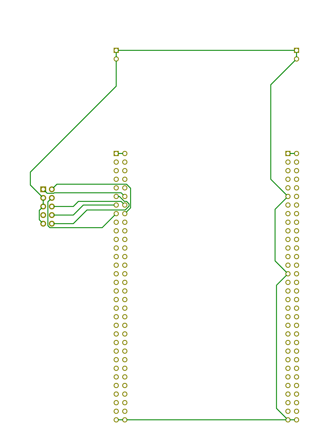
AdapterBoard is an open-source printed circuit board by AntonKrug, from the AntonKrug/akJtagPlusPlus repository on GitHub, published under the GPL-2.0 licence. It is a 2-layer board with 2 parts on 121 nets, routed with 56 tracks and 0 vias.
It belongs with the interfaces and adapters boards and the STM32 boards of this library.
Experimental JTAG dongle implemented in C++
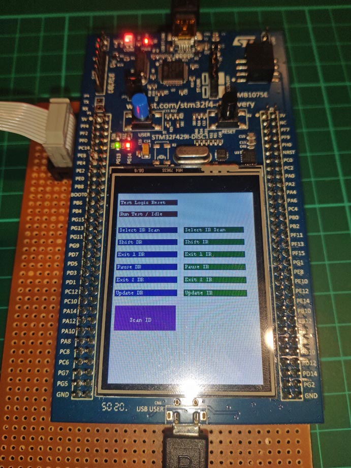
Allowing users to interact with JTAG enabled devices with USB, or in a standalone mode with LCD (and touch screen).
Limited to only minimalistic official (vanila) JTAG specification (no custom vendor commands) and 3.3V based devices. However it's possible to convert it to different voltages, or allow level conversion to range of voltages. And adding protocols/commands is possible as well if their specification is published.




The JTAG signals are bitbanged in SW, but written in assembly to make sure that the duty cycle stays the way it's expected as C/C++ can produce fast code, but it wouldn't gurantee the timing of the signals. In my assembly the sampling of read signals is happening around 2/3 of the clock period.
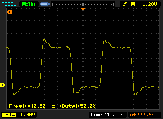
Currently the TCK runs 10.5MHz and around 50% duty cycle. For example if I wanted to have 8MHz exactly, then I couldn't have exact 50% duty cycle, because 168MHz / 8MHz is 21 clocks per period and can't be split evenly to 50:50 and small deviation from 50% duty cycle is necesary for some TCK frequencies.
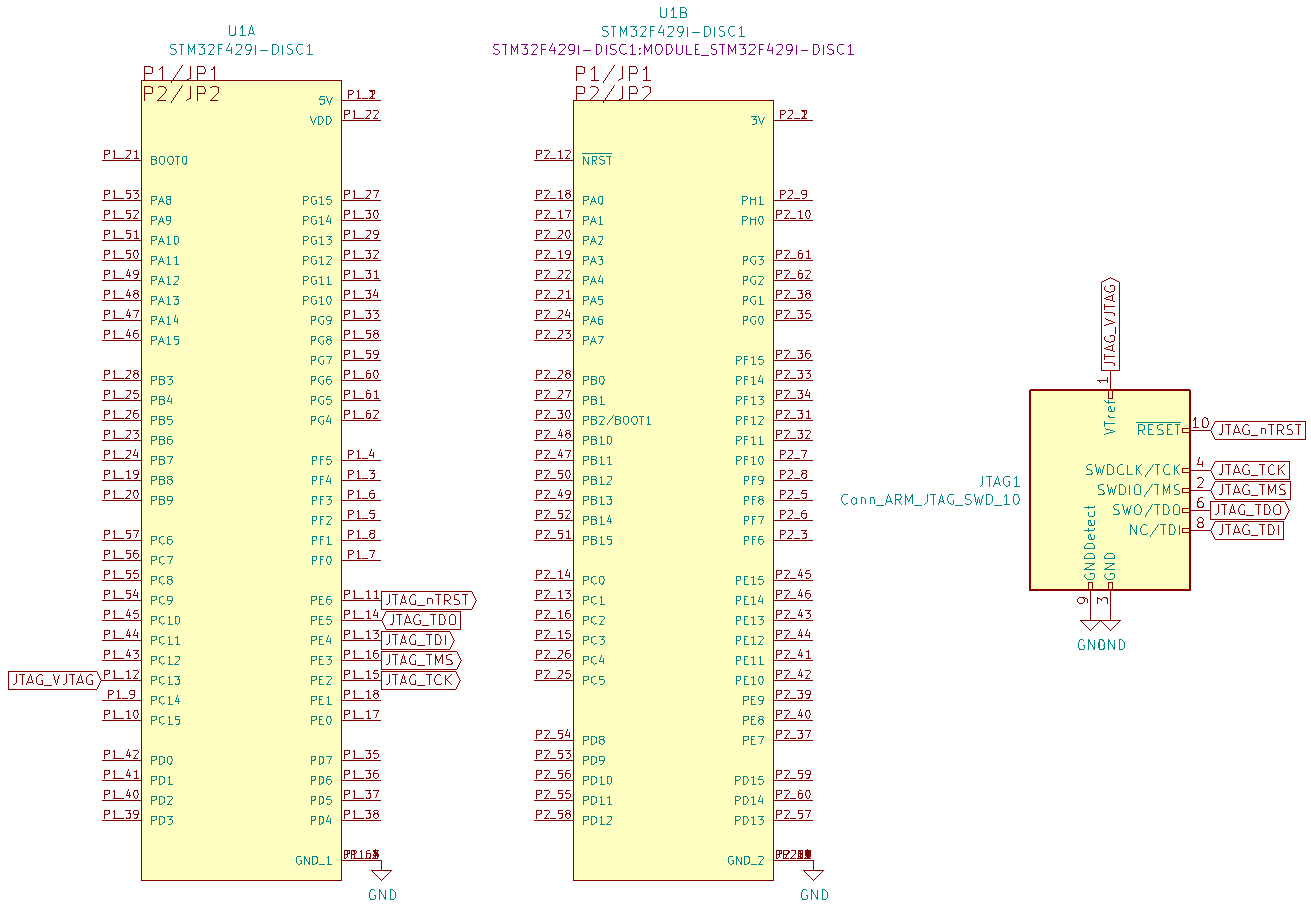
Based upon STM32F429ZI-DISC1 devboard with small daughter board connected to it (schematics/board below). To build the binaries, the project needs to be imported to a STM32cubeIDE 1.6 workspace and built with a Ctrl + B.
KiCad project files are located in the schematics folder.
Is implemented by using the STM32F429ZI-DISC1 USB port, PID:VID has to be determined yet. The class of device is HID, with fairly small report size (32bytes) and no extra drivers are necesary (bundled drivers with the OS are fine) and application can use HID RAW APIs to interact with the device directly.
https://en.wikipedia.org/wiki/Joint_Test_Action_Group
https://en.wikipedia.org/wiki/JTAG
http://openocd.org/doc/html/Reset-Configuration.html
| Qty | Value | Footprint | References |
|---|---|---|---|
| 1 | Conn_ARM_JTAG_SWD_10 | Connector_PinHeader_2.54mm:PinHeader_2x05_P2.54mm_Vertical | JTAG1 |
| 1 | STM32F429I-DISC1 | STM32F429I-DISC1:MODULE_STM32F429I-DISC1 | U1 |
hzeller/rpi-rgb-led-matrix
Controlling up to three chains of 64x64, 32x32, 16x32 or similar RGB LED displays using Raspberry Pi GPIO


adamws/kicad-kbplacer
KiCad plugin for automatic keyboard's key placement and routing

Luos-io/luos_engine
Open-source and real-time orchestrator for cyber-physical-systems, to easily design, test and deploy embedded applications and digital twins.

NVNTLabs/switch2-SDEX2M2
Micro SD Express to M.2 NVME Adapter for Nintendo Switch 2

BlueSCSI/BlueSCSI-v2
BlueSCSI v2/Ultra - an open source, open hardware, SCSI emulator using the Pi Pico PR2040 and Pico 2 RP2350

ohmtech-rdi/eurorack-blocks
Software to Hardware Prototyping for Eurorack using C++, Max/Gen~ or Faust

2 parts. The full list of its parts is on this page, with links to each part's symbol and footprint where PCBKit's library has them.
From the AntonKrug/akJtagPlusPlus repository on GitHub, at the commit this page was made from: the board is schematics/adapterBoard/adapterBoard.kicad_pcb. PCBKit opens the board in the browser, with nothing to install.
Its repository publishes it under the GPL-2.0 licence: you may reuse it on that licence's terms (keep the author's notice, and for a copyleft licence share your changes alike).