


4 layers96 × 172 mm

Low-cost MIDI Drum Trigger Interface based on ATMEGA 2560
Drumset is an open-source printed circuit board by AntonioJojoto, from the AntonioJojoto/MIDI-Drum-Trigger-Interface repository on GitHub. It is a 2-layer board with 176 parts on 153 nets.
It is built around the TL082 and LMC7660N. Its parts include 41 capacitors, 35 resistors, 23 connectors, 18 diodes and 16 ICs.
Many people may not know this, but drums are expensive, and if you live in an apartment, you can't just buy a cheap acoustic set and play, as your neighbors will call the police before you can finish playing your first song because an acoustic set can easily reach +110 dB.
However, there is another option, electronic drums. They are so silent that your roommates won't even complain (if you play at 3AM they might). But there is one big drawback to edrums, they are too expensive.
A low-tier edrum can go around 400€, I currently own a Yamaha DTX450k and I got a deal for it at 440€, as it normally goes for 550€ and when I was staring to practice it was OK, but then I got the chance to practice for a year on a acoustic set, and when I had to return to my cheap set I started to notice the drawback of cheap electronic drumsets.
Here are some problems that you may encounter when you play a cheap electronic set:
Sure, all of these problems may disappear as you upgrade to a more expensive drum set, but you will have to spend around 1200€. But even then, it will still be a mid-tier electronic drumset.
The best option, in my opinion, is to convert an acoustic set into an electronic one. If you already have an acoustic set or if you don't have one, as you can get one for 100€ or 200€. Now, there are two options for electronic conversion, buy the triggers and cymbals or go the DIY route, which is much cheaper. Although there is one expensive component that all the DIY guides asks for, the Drum Module.
It is normally the most expensive component in every drumset. The job of this component is critical, read the signals from the triggers and make a sound accordingly. Drum modules can go for around 300€ to 700€, but instead of buying a module that produce a mediocre sound, you should buy or make a trigger interface, is the same a drum module but instead of producing the sounds by itself, it sends MIDI notes to your computer, which will always produce better sound than even the most expensive modules.
Trigger Interfaces are much cheaper, the DDrum Trigger Interface will work perfectly for only 170€, but you can even make this component yourself.
DISCLAIMER: From now on, the guide will center on build the interface, in the following months a guide on DIY trigger and cymbals will be available. But from now, there is plenty of information online.
There are many Arduino drum modules online, but a common problem in all of them is the latency, I find that an Arduino isn't fast enough to process the raw piezo signal from several channels, which is the approach that many people follow when making the interface.
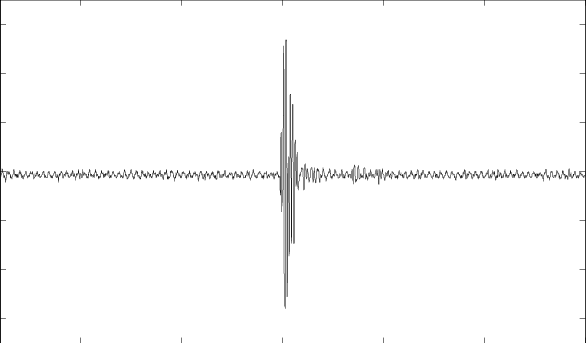
As seen in the picture, the peak of a piezo may only occur in the span of 100us. So the microcontroller may not read the channel at just the peak, so it will send no MIDI value at all, or send a wrong value. That is why in my desing I decided to add a peak detector circuit per channel.
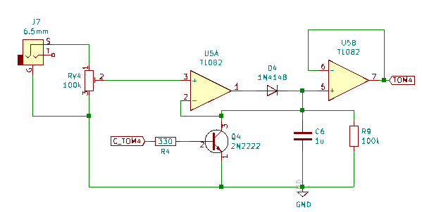
This circuit maintains the highest voltage from the piezo, so the voltage of the peak will be available for the uC to be read. Once the peak value has been registered, the capacitor will be discharged through the transistor, reseting the peak detector.
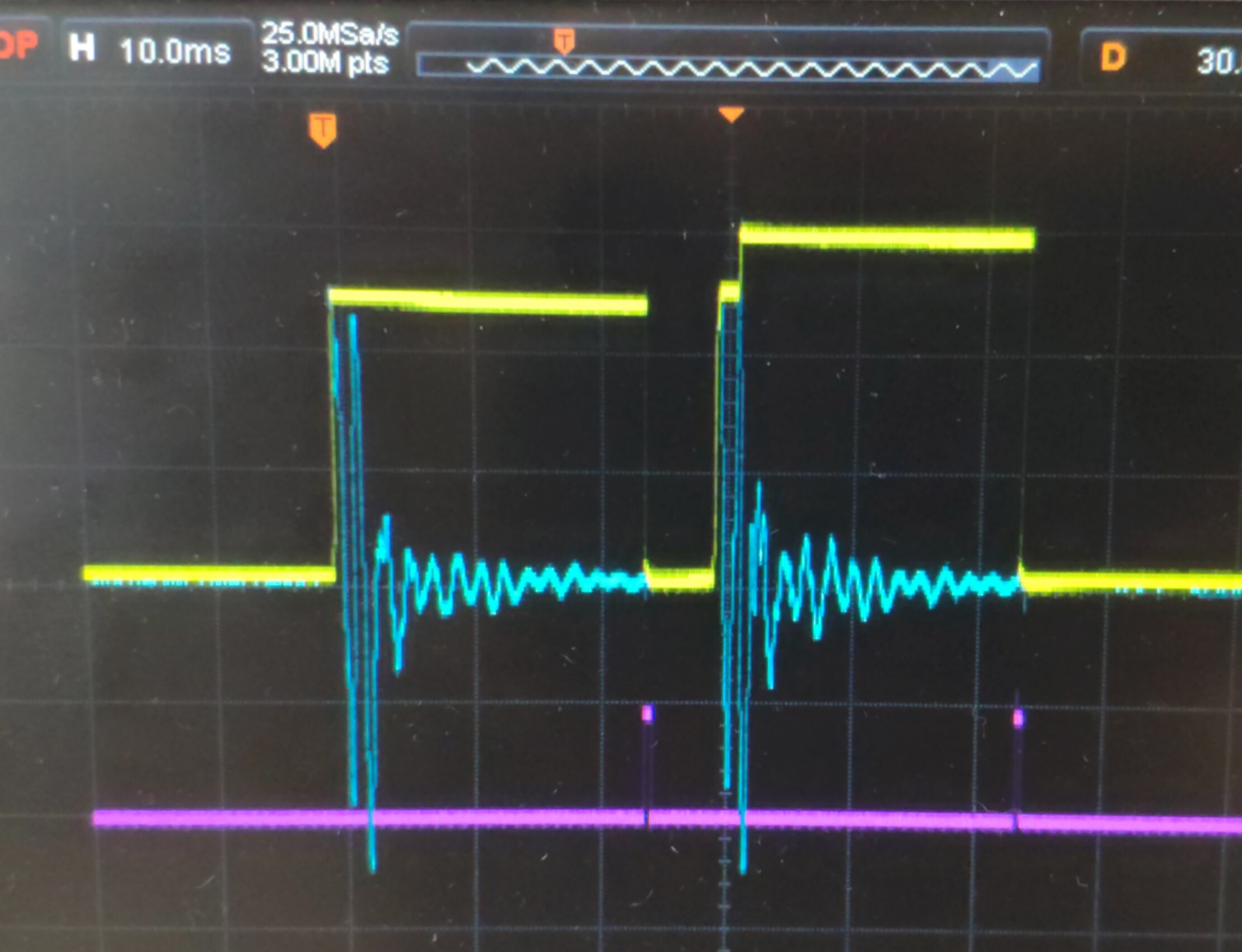
Once the uC detects a value on the channels higher than a given threshold, it wait a couple of milliseconds for the signal to reach the peak, this period is called scan time, after that, the value of the channel is read. But to stop retriggering, the uC won't clear the detector once a dead time has finished. All of these values are standarts from drum modules, and they can be set from channel to channel.
Using this method, we ensure that only the peak value of the piezo will be read, also no hits will be lost because the uC can read each channel at its own pace. In this example, the hit was a flam, and it registered both hits, although they were 30 milliseconds apart.
This desing is centered arround the AtMega 2560, as I want more than 6 channels for a full electronic set. But an AtMega328p can also be used, it depends on the number of channels that you want to use.
| Qty | Value | Footprint | References |
|---|---|---|---|
| 20 | 100n | Capacitor_THT:C_Disc_D3.8mm_W2.6mm_P2.50mm | C18, C19, C20, C21, C22, C23, C24, C25, C26, C27, C28, C29, C30, C31, C32, C33 +4 |
| 18 | 1N4148 | Diode_THT:D_DO-35_SOD27_P10.16mm_Horizontal | D1, D2, D3, D4, D5, D6, D7, D10, D11, D12, D13, D14, D15, D16, D17, D18 +2 |
| 15 | 100k | Potentiometer_THT:Potentiometer_Bourns_3266Y_Vertical | RV1, RV2, RV3, RV4, RV6, RV7, RV8, RV9, RV10, RV11, RV12, RV13, RV14, RV15, RV16 |
| 15 | 100k | Resistor_THT:R_Axial_DIN0207_L6.3mm_D2.5mm_P10.16mm_Horizontal | R5, R6, R7, R9, R13, R14, R15, R19, R20, R21, R29, R30, R31, R34, R35 |
| 15 | 1u | Capacitor_THT:C_Disc_D8.0mm_W5.0mm_P5.00mm | C3, C4, C5, C6, C7, C8, C9, C10, C11, C12, C13, C14, C15, C16, C17 |
| 15 | 2N2222 | Package_TO_SOT_THT:TO-92_Inline_Wide | Q1, Q2, Q3, Q4, Q5, Q6, Q7, Q8, Q9, Q10, Q11, Q12, Q13, Q14, Q15 |
| 15 | 330 | Resistor_THT:R_Axial_DIN0207_L6.3mm_D2.5mm_P10.16mm_Horizontal | R1, R2, R3, R4, R10, R11, R12, R16, R17, R18, R26, R27, R28, R32, R33 |
| 15 | TL082 | Package_DIP:DIP-8_W7.62mm_Socket | U2, U3, U4, U5, U6, U7, U8, U9, U10, U11, U12, U13, U14, U15, U16 |
| 10 | 6.5mm | Connector_Audio:Jack_6.35mm_Neutrik_NRJ6HM-1-AU_Horizontal | J4, J5, J6, J7, J14, J15, J16, J21, J22, J23 |
| 4 | 10k | Resistor_THT:R_Axial_DIN0207_L6.3mm_D2.5mm_P10.16mm_Horizontal | R22, R23, R24, R25 |
| 4 | 10u | Capacitor_THT:CP_Radial_D6.3mm_P2.50mm | C1, C2, C40, C41 |
| 4 | 3.5mm | Connector_Audio:Jack_3.5mm_PJ320D_Horizontal | J17, J18, J19, J20 |
| 2 | 10u | Capacitor_THT:C_Disc_D3.8mm_W2.6mm_P2.50mm | C36, C37 |
| 1 | 0_OK | Button_Switch_THT:SW_PUSH_6mm_H4.3mm | SW7 |
| 1 | 1 | Button_Switch_THT:SW_PUSH_6mm_H4.3mm | SW1 |
| 1 | 10k | Potentiometer_THT:Potentiometer_Piher_PT-10-V05_Vertical | RV5 |
| 1 | 12_11 | Connector_PinHeader_2.54mm:PinHeader_1x02_P2.54mm_Vertical | J11 |
| 1 | 2 | Button_Switch_THT:SW_PUSH_6mm_H4.3mm | SW5 |
| 1 | 220 | Resistor_THT:R_Axial_DIN0207_L6.3mm_D2.5mm_P10.16mm_Horizontal | R8 |
| 1 | 3 | Button_Switch_THT:SW_PUSH_6mm_H4.3mm | SW9 |
| 1 | 4 | Button_Switch_THT:SW_PUSH_6mm_H4.3mm | SW2 |
| 1 | 5 | Button_Switch_THT:SW_PUSH_6mm_H4.3mm | SW6 |
| 1 | 5_4_3_2_1 | Connector_PinHeader_2.54mm:PinHeader_1x05_P2.54mm_Vertical | J10 |
| 1 | 6 | Button_Switch_THT:SW_PUSH_6mm_H4.3mm | SW10 |
| 1 | 7 | Button_Switch_THT:SW_PUSH_6mm_H4.3mm | SW4 |
| 1 | 8 | Button_Switch_THT:SW_PUSH_6mm_H4.3mm | SW8 |
| 1 | 9 | Button_Switch_THT:SW_PUSH_6mm_H4.3mm | SW12 |
| 1 | Clear_Pins_Left | Connector_PinHeader_2.54mm:PinHeader_1x08_P2.54mm_Vertical | J3 |
| 1 | Clear_Pins_Right | Connector_PinHeader_2.54mm:PinHeader_1x08_P2.54mm_Vertical | J9 |
| 1 | Cymbal_Switches | Connector_PinHeader_2.54mm:PinHeader_1x05_P2.54mm_Vertical | J1 |
| 1 | First_Analog_Channels | Connector_PinHeader_2.54mm:PinHeader_1x08_P2.54mm_Vertical | J2 |
| 1 | Keypad | Connector_PinHeader_2.54mm:PinHeader_1x07_P2.54mm_Vertical | J13 |
| 1 | LCD | Connector_PinHeader_2.54mm:PinHeader_1x16_P2.54mm_Vertical | J12 |
| 1 | LEFT | Button_Switch_THT:SW_PUSH_6mm_H4.3mm | SW3 |
| 1 | LMC7660 | Package_DIP:DIP-8_W7.62mm_Socket | U1 |
| 1 | Last_Analog_Channels | Connector_PinHeader_2.54mm:PinHeader_1x08_P2.54mm_Vertical | J8 |
| 1 | RIGH | Button_Switch_THT:SW_PUSH_6mm_H4.3mm | SW11 |
176 parts, built around the TL082 and LMC7660N. The full list of its parts is on this page, with links to each part's symbol and footprint where PCBKit's library has them.
From the AntonioJojoto/MIDI-Drum-Trigger-Interface repository on GitHub, at the commit this page was made from: the board is KICAD/Drumset.kicad_pcb. PCBKit opens the board in the browser, with nothing to install.
Its repository states no licence, so its author keeps all rights: ask AntonioJojoto before reusing the design.


bc-kim/PCB_KiCAD
Tips Footprint of the resisotor and capacitor should be assigned aforetime because assigning those are comfusing when lots of reisistor and capacitors are used. 3. Reference: https://wikidocs.net/103412


AresEnsea/2324_Projet2A_AresCFR
Ce repository GitHub regroupe l'ensemble des projets & documents réalisés par l'association Ares pour la Coupe de France de Robotique 2024 – Farming Mars.
