2 layers100 × 80 mm
 antelliJ/KeychainPCB
Creating a keychain PCB
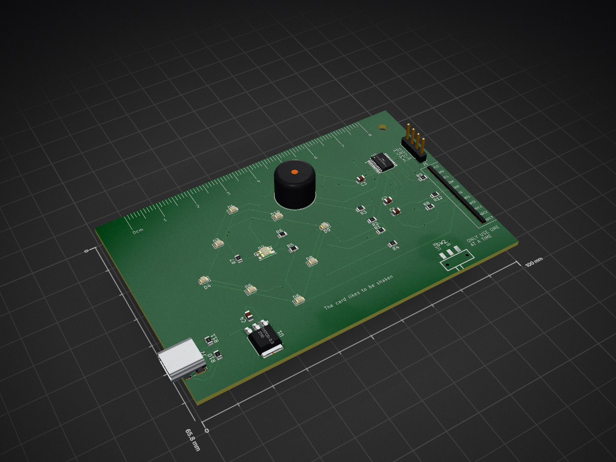
KeychainProj is an open-source printed circuit board by antelliJ, from the antelliJ/KeychainPCB repository on GitHub, published under the MIT licence. It is a 2-layer board of 100 × 65.8 mm with 34 parts on 38 nets, routed with 316 tracks and 41 vias.
It is built around the AMS1117CD-3.3 and LIS3DH. Its parts include 12 resistors, 9 diodes, 4 capacitors, 3 ICs and 2 connectors. It belongs with the RISC-V boards of this library.


Creating a keychain PCB badge
This is a personalized PCB that aims to be carried around on a keychain, a fun PCB badge similar to the ones at opensauce. I hope this could be an interesting way to introduce myself in an interactive manner if I'm at any tech conferences or the like.
Uses either a CR2032 or USB-C to power a CH32V003 MCU, toggled between using a 2 way switch.
a LIS331HH communicates to the board to activate the LED's based on the motion associated.
Programmable input is available through the headers.
The back silkscreen plugs my github account through a link and a QR code
The front silkscreens include some random things I thought would be interesting, like a ruler and fun hints to get people interested in what the board can actually do
\PCB\ includes files relevant for the pcb and manufacturing.
\PCB\production are the files used for PCB manufacturing
\Code\ is intended for all the code, which is basically empty at the moment. Eventually it will have the custom firmware.
Shake to wake, various taps can cycle through the different animations. One of which that would show a morse code representation of my name, among other small animations with the leds.
A nicely formatted excel sheet is provided at \PCB\production\Keychain-Bom.xlsx
The below is just a static version of that...
| Designator | Footprint | Quantity | Value | JLCPCB Part # | MPN |
|---|---|---|---|---|---|
| BT1 | BatteryHolder_Keystone_1058_1x2032 | 1 | Battery_Cell | ||
| BZ1 | Buzzer_12x9.5RM7.6 | 1 | Piezo buzzer (passive) | C76871 | PS1240P02BT |
| C1, C3 | 0805 | 2 | 100nF | C49678 | CC0805KRX7R9BB104 |
| C2, C4 | 0805 | 2 | 10uF | C15850 | CL21A106KAYNNNE |
| D1, D10, D3, D4, D5, D6, D8, D9 | 0805 | 8 | Red LED | C84256 | NCD0805R1 |
| D2 | LED_RGB_1210 | 1 | LED_RABG | C375572 | E6C1209RGBC3UDA |
| J1 | PinHeader_1x04_P2.54mm_Vertical | 1 | Conn_01x04_Pin | C52016392 | HX PH254-01-04-Z-L11.5 straight pin header |
| J2 | USB_C_Receptacle_GCT_USB4085 | 1 | USB_C_Receptacle_PowerOnly_6P | C668623 | TYPE-C 6P(073) |
| R1, R2, R3, R4 | 0805 | 4 | 100 | C17408 | 0805W8F1000T5E |
| R10, R11 | 0805 | 2 | 5k1 | C27834 | 0805W8F5101T5E |
| R12, R8, R9 | 0805 | 3 | 4k7 | C17673 | 0805W8F4701T5E |
| R7 | 0805 | 1 | 330 (RK led) | C17437 | 0805W8F1200T5E |
| SW1 | SW-SMD_MST-12D18G4-SPDT-SLIDE-SWITCH | 1 | MST-12D18G4 SPDT SLIDE SWITCH | C49023767 | MST-12D18G4 SPDT Slide Switch |
| U1 | TO-252-3_TabPin2 | 1 | AMS1117CD-3.3 | C6186 | AMS1117-3.3 |
| U2 | LGA-16_3x3mm_P0.5mm_LayoutBorder3x5y | 1 | LIS3DH | C15134 | LIS3DHTR |
| U4 | TSSOP-20_4.4x6.5mm_P0.65mm | 1 | CH32V003FxPx | C5187096 | CH32V003F4P6 |
** You may notice that r5 and r6 are missing, I included them in the schematic for the blue and green LEDs in the center RGB LED, but I don't think there is enough power for it to make it worth it? If anything it would just reduce the brightness from whatever it already is. Those pads should just be wired together if using the gerber files as is.
A lot of things were picked up on the way of creating this project, with it being my first proper PCB
used Table to Markdown to make the above BOM in the readme
| Qty | Value | Footprint | References |
|---|---|---|---|
| 8 | LED | LED_SMD:LED_0805_2012Metric | D1, D3, D4, D5, D6, D8, D9, D10 |
| 4 | 100 | Resistor_SMD:R_0805_2012Metric | R1, R2, R3, R4 |
| 3 | 4k7 | Resistor_SMD:R_0805_2012Metric | R8, R9, R12 |
| 2 | 0 | Resistor_SMD:R_0805_2012Metric | R5, R6 |
| 2 | 100nF | Capacitor_SMD:C_0805_2012Metric | C1, C3 |
| 2 | 10uF | Capacitor_SMD:C_0805_2012Metric | C2, C4 |
| 2 | 5k1 | Resistor_SMD:R_0805_2012Metric | R10, R11 |
| 1 | 330 | Resistor_SMD:R_0805_2012Metric | R7 |
| 1 | AMS1117CD-3.3 | Package_TO_SOT_SMD:TO-252-3_TabPin2 | U1 |
| 1 | Battery_Cell | Battery:BatteryHolder_Keystone_1058_1x2032 | BT1 |
| 1 | Buzzer | Buzzer_Beeper:Buzzer_12x9.5RM7.6 | BZ1 |
| 1 | CH32V003FxPx | Package_SO:TSSOP-20_4.4x6.5mm_P0.65mm | U4 |
| 1 | Conn_01x04_Pin | Connector_PinHeader_2.54mm:PinHeader_1x04_P2.54mm_Vertical | J1 |
| 1 | LED_RABG | LED_SMD:LED_RGB_1210 | D2 |
| 1 | LIS3DH | ModuleLibrary:LIS3DH_Aliexpress_Module | U2 |
| 1 | MST-12D18G4 SPDT SLIDE SWITCH | Newsymbols:SW-SMD_MST-12D18G4-SPDT-SLIDE-SWITCH | SW2 |
| 1 | MountingHole | MountingHole:MountingHole_3mm | H1 |
| 1 | USB_C_Receptacle_PowerOnly_6P | Connector_USB:USB_C_Receptacle_GCT_USB4085 | J2 |


deep-th/CAN_Logger
This is a compact and reliable CAN logger board built for automotive and industrial applications. It features the ESP32-S3 microcontroller and MCP25625 CAN controller with integrated transceiver, supporting two…

Hugondon/Proyecto-Trayectorias
Códigos utilizados para el proyecto de ingeniería

carlassaraf/tp_analyzer
RP2350A based firmware for a three-phase analyzer instrument running FreeRTOS and LVGL UI

Casual-Coder-dev/ESP32-Mini-1-N8-Devboard-
This project contains the pcb of an ESP32 Mini 1 N8 Development board that is suitable for your needs.

It measures 100 × 65.8 mm and has 2 copper layers, 1.6 mm thick.
34 parts, built around the AMS1117CD-3.3 and LIS3DH. The full list of its parts is on this page, with links to each part's symbol and footprint where PCBKit's library has them.
From the antelliJ/KeychainPCB repository on GitHub, at the commit this page was made from: the board is PCB/keychainProj.kicad_pcb and its schematic PCB/keychainProj.kicad_sch. PCBKit opens the board in the browser, with nothing to install.
Its repository publishes it under the MIT licence: you may reuse it on that licence's terms (keep the author's notice, and for a copyleft licence share your changes alike).