2 layers18.5 × 26 mm
24g2usb rp2350zero
joypad-ai/joypad-os
Universal controller firmware for building adapters, dongles, and custom controllers.
4 parts1.7kApache-2.0
 andrewteall/pi-eeprom-programmer20
A Raspberry Pi GPIO EEPROM reader and writer
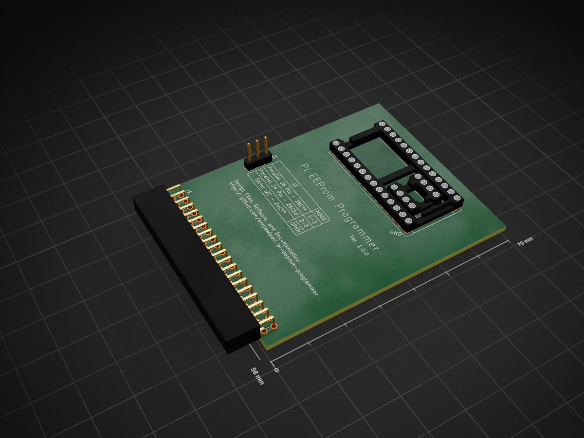
Pi eeprom programmer is an open-source printed circuit board by andrewteall, from the andrewteall/pi-eeprom-programmer repository on GitHub, published under the MIT-0 licence. It is a 2-layer board of 70 × 56 mm with 4 parts on 41 nets, routed with 181 tracks and 0 vias.
Its parts include 2 ICs and 2 connectors. It belongs with the interfaces and adapters boards of this library.
A way to write Parallel and Serial EEPROMs using the Raspberry Pi GPIO pins.
Before reading or writing any EEPROM you have to build the apprpriate circuit to do so.
You'll need a breadboard, jumper wires, and a 40-pin connector and cable to attach to the GPIO pins of the Raspberry Pi and a way to connect the opposite end to the breadboard. I like using one of the many Raspberry Pi GPIO Breakout boards available.
Serial I2C EEPROM Circuit
            Raspberry Pi GPIO                         I2C DIP8 Serial EEPROM
            3V3  (1) (2)  5V                   GND <-  A0 | (1) (8) | VCC -> 3V3
 SDA 5 -> GPIO2  (3) (4)  5V                   GND <-  A1 | (2) (7) | WP  -> GPIO16 (36)
 SCL 6 -> GPIO3  (5) (6)  GND                  GND <-  A2 | (3) (6) | SCL -> GPIO2  (3)
          GPIO4  (7) (8)  GPIO14               GND <- GND | (4) (5) | SDA -> GPIO3  (5)
            GND  (9) (10) GPIO15
         GPIO17 (11) (12) GPIO18
         GPIO27 (13) (14) GND
         GPIO22 (15) (16) GPIO23
            3V3 (17) (18) GPIO24
         GPIO10 (19) (20) GND
          GPIO9 (21) (22) GPIO25
         GPIO11 (23) (24) GPIO8
            GND (25) (26) GPIO7
          GPIO0 (27) (28) GPIO1
          GPIO5 (29) (30) GND
          GPIO6 (31) (32) GPIO12
         GPIO13 (33) (34) GND
         GPIO19 (35) (36) GPIO16 -> 7 WP
         GPIO26 (37) (38) GPIO20
            GND (39) (40) GPIO21
Parallel EEPROM Circuit
 IC  |   Raspberry Pi GPIO      | IC  |        Pi  |  DIP28 Parallel EEPROM  |  Pi         | DIP24 Parallel EEPROM
          3V3  (1) (2)  5V            |  (7)  GPIO4 <-  A14  (1) (28) VCC  -> 5V           |
I/O3 -> GPIO2  (3) (4)  5V            | (11) GPIO17 <-  A12  (2) (27) /WE  -> GPIO14 (8)   |
I/O4 -> GPIO3  (5) (6)  GND           | (13) GPIO27 <-   A7  (3) (26) A13  -> GPIO15 (10)  | VCC -> 5V
A14 ->  GPIO4  (7) (8)  GPIO14 -> /WE | (15) GPIO22 <-   A6  (4) (25) A8   -> GPIO18 (12)  |
          GND  (9) (10) GPIO15 -> A13 | (19) GPIO10 <-   A5  (5) (24) A9   -> GPIO23 (16)  |
A12 -> GPIO17 (11) (12) GPIO18 -> A8  | (21)  GPIO9 <-   A4  (6) (23) A11  -> GPIO24 (18)  | /WE -> GPIO14 (8)
 A7 -> GPIO27 (13) (14) GND           | (23) GPIO11 <-   A3  (7) (22) /OE  -> GPIO25 (22)  |
 A6 -> GPIO22 (15) (16) GPIO23 -> A9  | (27)  GPIO0 <-   A2  (8) (21) A10  -> GPIO8  (24)  |
          3V3 (17) (18) GPIO24 -> A11 | (29)  GPIO5 <-   A1  (9) (20) /CE  -> GPIO7  (26)  |
 A5 -> GPIO10 (19) (20) GND           | (31)  GPIO6 <-   A0 (10) (19) I/O7 -> GPIO1  (28)  |
 A4 ->  GPIO9 (21) (22) GPIO25 -> /OE | (33) GPIO13 <- I/O0 (11) (18) I/O6 -> GPIO12 (32)  |
 A3 -> GPIO11 (23) (24) GPIO8  -> A10 | (35) GPIO19 <- I/O1 (12) (17) I/O5 -> GPIO16 (36)  |
          GND (25) (26) GPIO7  -> /CE | (37) GPIO26 <- I/O2 (13) (16) I/O4 -> GPIO3  (38)  |
 A2 ->  GPIO0 (27) (28) GPIO1  -> I/O7|          GND <- GND (14) (15) I/O3 -> GPIO2  (40)  |
 A1 ->  GPIO5 (29) (30) GND           |
 A0 ->  GPIO6 (31) (32) GPIO12 -> I/O6|
I/O0 ->GPIO13 (33) (34) GND           |
I/O1 ->GPIO19 (35) (36) GPIO16 -> I/O5|
I/O2 ->GPIO26 (37) (38) GPIO20        |
          GND (39) (40) GPIO21 ->     |
Alternatively a pcb can be ordered from any of the various manufacturers from the zipped gerbers contained in hardware/manufacturing/pi-eeprom-programmer-v.v.v.zip.
If you plan to use serial EEPROMs you'll need to setup I2C on the Raspberry Pi. Adafruit has a great tutorial. Typically, if you're just using parallel EEPROM's then you can proceed to the next step. However, if the libgpiod2 and libgpiod-dev packages are not installed on your Raspberry Pi you will need to to install them.
Download and compile the programmer software
git clone git@github.com:andrewteall/pi-eeprom-programmer.git
cd pi-eeprom-programmer/software
make
Install piepro
make installThat's it. You should be able to start reading and writing EEPROMs.
If you've recreated the circuit exactly from above or are using the pcb the IC should be installed so that the bottom left pin of the IC is aligned to the bottom left of the circuit.
To read an EEPROM, after building the circuit and inserting the IC, run the command
piepro -d -m EEPROM_MODELWhere EEPROM_MODEL is typically the IC's part number such as at28c64, xl2816, at24c02, etc... This will dump the EEPROM's contents to standard out in a pretty format. If you wish to start or limit the addresses dumped you may specify the -s ADDRESS or -l ADDRESS flags respectively.
To write to an EEPROM, after building the circuit and inserting the IC, run the command
piepro -w file.bin -m EEPROM_MODELTo compare you EEPROM to the file after writing, run the command
piepro -c file.bin -m EEPROM_MODELWhere EEPROM_MODEL is typically the IC's part number such as at28c64, xl2816, at24c02, etc...
Most modern EERPOMs will work but if you're using an obscure EEPROM you need to makes sure it can operate on 5v Vcc and 3.3v levels if it's a parallel EEPROM and 3.3v Vcc and 3.3v levels if it's a serial EEPROM.
Usage: piepro [options]
Options:
 -c FILE,   --compare FILE  Compare FILE and EEPROM and print number of differences.
            --chipname      Specify the chipname to use. Default: gpiochip0
 -d [N],    --dump [N]      Dump the contents of the EEPROM,
                            0=PRETTY_WITH_ASCII, 1=BINARY, 2=TEXT, 3=LABELED, 4=PRETTY. Default: PRETTY_WITH_ASCII
 -e [N],    --erase [N]     Erase eeprom with specified byte. Default: 0xFF
 -f,        --force         Force writing of every byte instead of checking for existing value first.
 -id,       --i2c-device-id The address id of the I2C device.
 -h,        --help          Print this message and exit.
 -l N,      --limit N       Specify the maximum address to operate.
 -m MODEL,  --model MODEL   Specify EERPOM device model. Default: AT28C16.
            --no-validate-write
                            Do not perform a read directly after writing to verify the data was written.
 -r [N],    --read [N]      Read the contents of the EEPROM,
                            0=PRETTY_WITH_ASCII, 1=BINARY, 2=TEXT, 3=LABELED, 4=PRETTY. Default: PRETTY_WITH_ASCII
 -rb N,     --read-byte ADDRESS
                            Read From specified ADDRESS.
 -q [N],     --quick [N]    Operates on N bytes at once for reads. Page Size if unspecified or writes.
                            Implied --force and --no-validate-write.
 -s N,      --start N       Specify the minimum address to operate.
 -t,        --text          Interpret file as a text. Default: binary
                            Text File format:
[00000000]00000000 00000000If there's anything you'd like to add or find a bug please open an issue. If you'd like to implement those chages yourself please feel free to open a PR or fork the repository and make it your own.
This repository is licensed under the MIT-0 License for everything not contained in the hardware folder and it's sub folders. For all files and folders in the hardware folder and it's sub folders, they are licensed under CC0. You are free to use, modify, and distribute the project according to the terms of these licenses.
| Qty | Value | Footprint | References |
|---|---|---|---|
| 1 | 24C01-24C1024 | Package_DIP:DIP-8_W7.62mm_Socket | U2 |
| 1 | Conn_01x03 | Connector_PinHeader_2.54mm:PinHeader_1x03_P2.54mm_Vertical | J2 |
| 1 | Raspberry Pi GPIO Connector | Connector_PinSocket_2.54mm:PinSocket_2x20_P2.54mm_Horizontal | J1 |
| 1 | ZIF Socket | Package_DIP:DIP-28_W15.24mm_Socket | U1 |
It measures 70 × 56 mm and has 2 copper layers, 1.6 mm thick.
4 parts. The full list of its parts is on this page, with links to each part's symbol and footprint where PCBKit's library has them.
From the andrewteall/pi-eeprom-programmer repository on GitHub, at the commit this page was made from: the board is hardware/design/pi-eeprom-programmer.kicad_pcb and its schematic hardware/design/pi-eeprom-programmer.kicad_sch. PCBKit opens the board in the browser, with nothing to install.
Its repository publishes it under the MIT-0 licence: you may reuse it on that licence's terms (keep the author's notice, and for a copyleft licence share your changes alike).
joypad-ai/joypad-os
Universal controller firmware for building adapters, dongles, and custom controllers.


hackclub/OnBoard
💡 Join 1,000 teenagers and make your first PCB with a $100 grant!

tardate/LittleArduinoProjects
a collection of "Little Electronic & Arduino Projects", most involving electronics or an Arduino in one way or another!

drandyhaas/KiCadRoutingTools
A set of Python/Rust tools to aid routing in KiCad

osy/XG_Mobile_Station
Open source eGPU dock for ROG Ally and ROG Flow

Luos-io/luos_engine
Open-source and real-time orchestrator for cyber-physical-systems, to easily design, test and deploy embedded applications and digital twins.

NVNTLabs/switch2-SDEX2M2
Micro SD Express to M.2 NVME Adapter for Nintendo Switch 2