
4 layers58.5 × 58.5 mm
Transmitter
andrew153d/RemoteWelderController
A pair of devices meant to retrofit older welders with wireless connectivity. This document covers the usage and mechanical makeup, the cost overview can be found here.
111 parts1
A pair of devices meant to retrofit older welders with wireless connectivity. This document covers the usage and mechanical makeup, the cost overview can be found here.
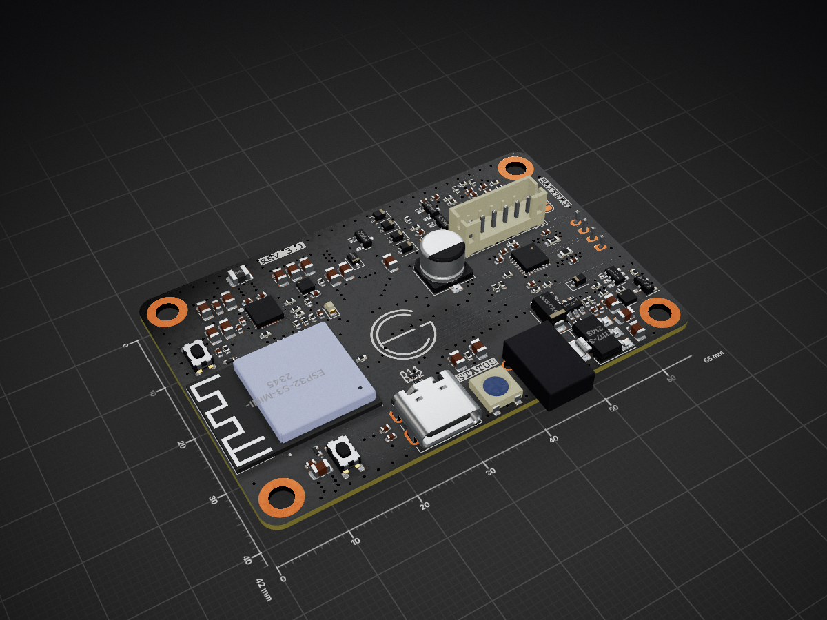
Receiver is an open-source printed circuit board by andrew153d, from the andrew153d/RemoteWelderController repository on GitHub. It is a 4-layer board of 65 × 42 mm with 131 parts on 125 nets, routed with 850 tracks and 320 vias.
It is built around the ESP32-S3-MINI-1-N8, TLV493DA1B6HTSA2 and DMG6602SVTQ, with the TPS22810DRV and WS2812B among its other parts. Its parts include 45 capacitors, 45 resistors, 15 diodes, 8 ICs and 4 transistors. It belongs with the ESP32 boards of this library.


A pair of devices meant to retrofit older welders with wireless connectivity. This document covers the usage and mechanical makeup, the cost overview can be found here. There is also a preview of the site at this link, note functionality is limited.
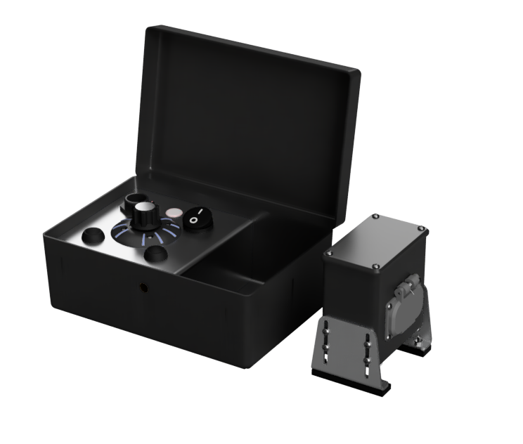
There are three main modes of operation: Standard, Web Control, and Extended Web Control
To enter standard control mode, toggle the Transmitter power switch to the 'ON' position and press the Power button on the Receiver. While the devices are searching for each other, their status LEDs will flash blue and will transition to solid green when connected. Rotation input on the control knob will result in proportional motion on the output shaft of the receiver.
Web Control Mode will allow the user to make use of the web interface to control the output of the receiver. Press the power button on the receiver to turn the device on. After the status LED flashes blue, hold the power button for 3 seconds or until the LED turns to solid green. Connect your phone to the wifi network named Weld_---, open a browser and go to 'Weld.local'.
Extended Web Control uses the Transmitter to host the webpage and repeats control to the receiver. After turning on both devices, hold both the up and down buttons for 3 seconds until the status LED turns green. Connect your phone to the Wifi network named Weld_--- and open the site 'Weld.Local'. In order to increase the usable distance, place the transmitter between the user and the receiver.
The webpage for control and configuration. Of course you can stay loyal to your brand while still bringing your welder into the modern world. The dial can be dragged to rotate, or the user can swipe the arrows at the bottom to rotate the knob. The lock button will match rotation on the output to the knob on the webpage. The align button will automatically measure the range of the output and scale the input accordingly. Settings and more configuration options can be accessed via the menu on the top left.



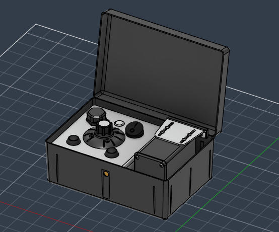
Top view of the pelican case with reciever stowed on the right side.
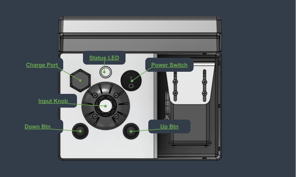
The charge port cap can be removed to expose the USBC port and charge the device.
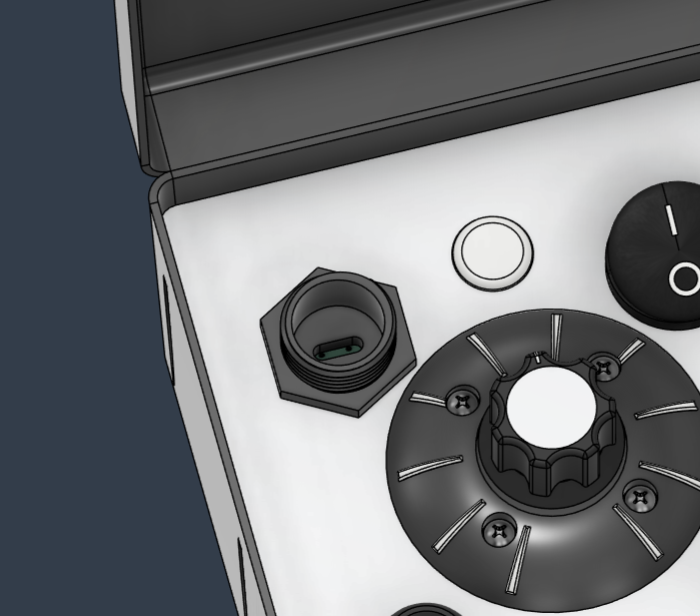
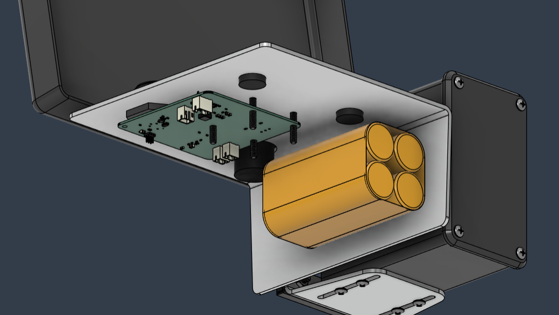
The circuit board and battery pack get mounted under the faceplate. Not shown is a cover to shield the electronics from debris under the faceplate.
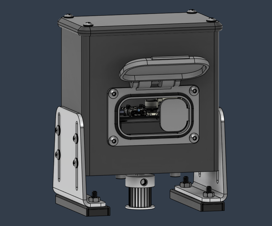
Receiver is shown without belt mechanism. The hatch is biased closed by a torsion spring and sealed against the surface with a O-ring.
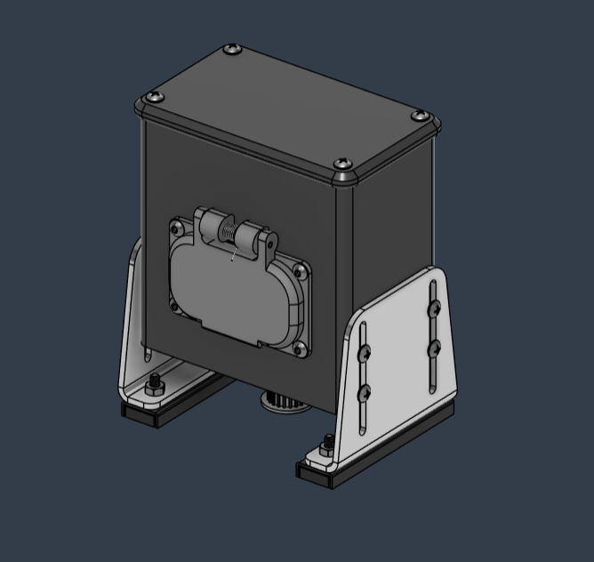
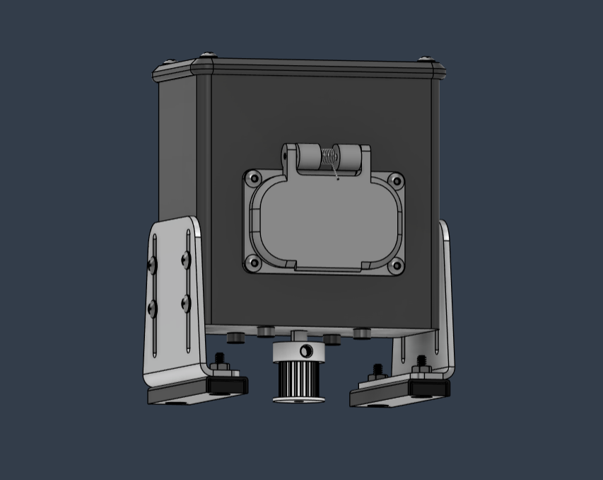
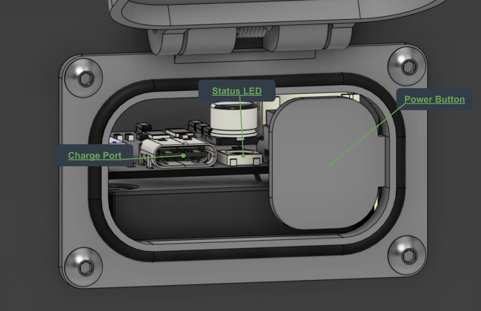
Shown below is the hatch on the receiver that exposes the charging port, status led, and power button. The power button serves multiple alternative functions described in the usage section.
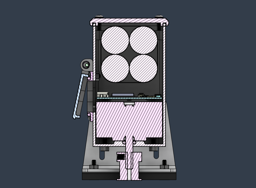
There are several seals on the receiver that maintain water resistance. The upper seal gets compressed between the upper cover and the case. There is also a seal on the access hatch as well as around the motor shaft.
| Qty | Value | Footprint | References |
|---|---|---|---|
| 13 | 10u | Capacitor_SMD:C_0805_2012Metric | C2, C3, C6, C10, C12, C13, C15, C16, C17, C18, C26, C33, C34 |
| 11 | 0.1u | Capacitor_SMD:C_0402_1005Metric | C1, C11, C29, C31, C35, C36, C39, C40, C44, C45, C47 |
| 10 | 100k | Resistor_SMD:R_0402_1005Metric | R7, R9, R11, R17, R18, R19, R20, R33, R39, R42 |
| 9 | 10k | Resistor_SMD:R_0402_1005Metric | R1, R2, R16, R34, R35, R36, R38, R41, R45 |
| 5 | 10 | Resistor_SMD:R_0402_1005Metric | R21, R22, R23, R24, R25 |
| 5 | 1N4148WQ-13-F | Diode_SMD:D_SOD-323 | D4, D7, D8, D9, D10 |
| 5 | 220nf | Capacitor_SMD:C_0402_1005Metric | C21, C22, C23, C24, C25 |
| 5 | TVN3V3B1S | Diode_SMD:D_0402_1005Metric | D11, D12, D13, D14, D15 |
| 4 | 100 | Resistor_SMD:R_0402_1005Metric | R10, R26, R28, R29 |
| 4 | 1u | Capacitor_SMD:C_0402_1005Metric | C27, C30, C32, C38 |
| 4 | MountingHole | MountingHole:MountingHole_3.2mm_M3_DIN965_Pad_TopBottom | H1, H2, H3, H4 |
| 3 | 5.1k | Resistor_SMD:R_0402_1005Metric | R6, R31, R32 |
| 3 | 5.1k | Capacitor_SMD:C_0402_1005Metric | R3, R4, R5 |
| 2 | 0.22u | Capacitor_SMD:C_0402_1005Metric | C42, C43 |
| 2 | 22u | Capacitor_SMD:C_0805_2012Metric | C37, C46 |
| 2 | 47n | Capacitor_SMD:C_0402_1005Metric | C4, C5 |
| 2 | 68m | Resistor_SMD:R_0603_1608Metric | R43, R44 |
| 2 | DMG6602SVTQ | Package_TO_SOT_SMD:TSOT-23-6 | U2, U3 |
| 2 | NMOS | Package_TO_SOT_SMD:SOT-23 | Q2, Q3 |
| 2 | TPS22810DRV | Package_SON:WSON-6-1EP_2x2mm_P0.65mm_EP1x1.6mm | U1, U5 |
| 1 | .1u | Capacitor_SMD:C_0402_1005Metric | C7 |
| 1 | 0 | Resistor_SMD:R_0402_1005Metric | R30 |
| 1 | 100p | Capacitor_SMD:C_0402_1005Metric | C28 |
| 1 | 10u | Capacitor_SMD:C_0603_1608Metric | C8 |
| 1 | 127k | Resistor_SMD:R_0402_1005Metric | R12 |
| 1 | 1825027-8 | Button_THT:SW2_1825027-C_TEC | SW3 |
| 1 | 1M | Resistor_SMD:R_0402_1005Metric | R8 |
| 1 | 1m | Resistor_SMD:R_0402_1005Metric | R27 |
| 1 | 1u | Inductor_SMD:L_1008_2520Metric | L1 |
| 1 | 20k | Resistor_SMD:R_0402_1005Metric | R40 |
| 1 | 2N7002 | Package_TO_SOT_SMD:SOT-23 | Q1 |
| 1 | 30.31k | Resistor_SMD:R_0402_1005Metric | R14 |
| 1 | 4.7u | Capacitor_SMD:C_0402_1005Metric | C9 |
| 1 | 47u | Capacitor_SMD:CP_Elec_6.3x5.4 | C41 |
| 1 | 5.24k | Resistor_SMD:R_0402_1005Metric | R13 |
| 1 | 6.04k | Resistor_SMD:R_0402_1005Metric | R15 |
| 1 | AZ1117-3.3 | Package_TO_SOT_SMD:SOT-223 | U7 |
| 1 | BQ76905 | Package_DFN_QFN:UQFN-20-1EP_3x3mm_P0.4mm_EP1.85x1.85mm | U6 |
| 1 | BQ76905_Bypass | Jumper:SolderJumper-2_P1.3mm_Open_RoundedPad1.0x1.5mm | JP1 |
| 1 | Boot | Switch:Tactile_5.5mmx2.85mm | SW2 |
| 1 | Conn_01x04 | Connector_JST:JST_PH_B4B-PH-K_1x04_P2.00mm_Vertical | J4 |
| 1 | D_Zener | Diode_SMD:D_SOD-323F | D5 |
| 1 | ESP32-S3-MINI-1-N8 | XCVR_ESP32-S3-MINI-1-N8:XCVR_ESP32-S3-MINI-1-N8 | U8 |
| 1 | EVVO SS16 | Diode_SMD:D_SMA | D6 |
| 1 | JST_PH | Connector_JST:JST_PH_B6B-PH-K_1x06_P2.00mm_Vertical | J3 |
| 1 | LED | Capacitor_SMD:C_0805_2012Metric | D2 |
| 1 | LED | LED_SMD:LED_0603_1608Metric | D1 |
| 1 | NP | Capacitor_SMD:C_0402_1005Metric | C14 |
| 1 | NP | Resistor_SMD:R_0402_1005Metric | R37 |
| 1 | PMOS | Package_TO_SOT_SMD:SOT-23 | Q4 |
| 1 | Reset | Switch:Tactile_5.5mmx2.85mm | SW1 |
| 1 | TLV493DA1B6HTSA2 | Package_TO_SOT_SMD:SOT-23-6 | U4 |
| 1 | USB_C_Receptacle_USB2.0 | Connector_USB:USB_C_Receptacle_JAE_DX07S016JA1R1500 | J1 |
| 1 | WS2812B | LED_SMD:LED_WS2812B_PLCC4_5.0x5.0mm_P3.2mm | D3 |
| 1 | ~ | Lipo_Charger:BQ25792 | BQ25792RQMR1 |
| 1 | ~ | Package_DFN_QFN:QFN-28_4x4mm_P0.5mm | A1 |
andrew153d/RemoteWelderController
A pair of devices meant to retrofit older welders with wireless connectivity. This document covers the usage and mechanical makeup, the cost overview can be found here.

skyler84-tildagon-addons/goosepansion
Untitled Goose Game inspired capacitive touch reversible goose honker

gocivici/trinteract
An open-source Arduino-compatible 3DOF Human Interface Device (HID)

BiggiePete/RTLS_VIC
Return to launch senior design kicad hardware repo for Vehicle In-flight Controller

i2cjak/Framework_Expansion_Cards
In which i2cjak creates a new expansion card design every day until he is given a NICE Framework laptop

meshsat/meshsat-fieldkit
MeshSat field kit hardware: the V1 kits as built, the V2 carrier PCB set for the Peli 1450 and the compact pocket-sized node (KiCad and OpenSCAD sources, generators, release files, build guides).


CodeLinaro-mirror/qcomlt_debugboard
96boards specifications compliant Mezzanine used to control the DC Input, USB VBUS, PWR/RST buttons and Debug UART via a single USB2.0 CDC interface.
It measures 65 × 42 mm and has 4 copper layers, 1 mm thick.
131 parts, built around the ESP32-S3-MINI-1-N8, TLV493DA1B6HTSA2, DMG6602SVTQ and TPS22810DRV. The full list of its parts is on this page, with links to each part's symbol and footprint where PCBKit's library has them.
From the andrew153d/RemoteWelderController repository on GitHub, at the commit this page was made from: the board is hardware/Receiver/Receiver.kicad_pcb and its schematic hardware/Receiver/Receiver.kicad_sch. PCBKit opens the board in the browser, with nothing to install.
Its repository states no licence, so its author keeps all rights: ask andrew153d before reusing the design.