
2 layers320 × 81.3 mm
Display and controls board
411568/Atmega8_FM_radio
Simple FM radio based on Atmega8 and TEA5767 module
103 parts3MIT
 anachrocomputer/LedHex
Programs and CAD files for the LED hex display PCB.
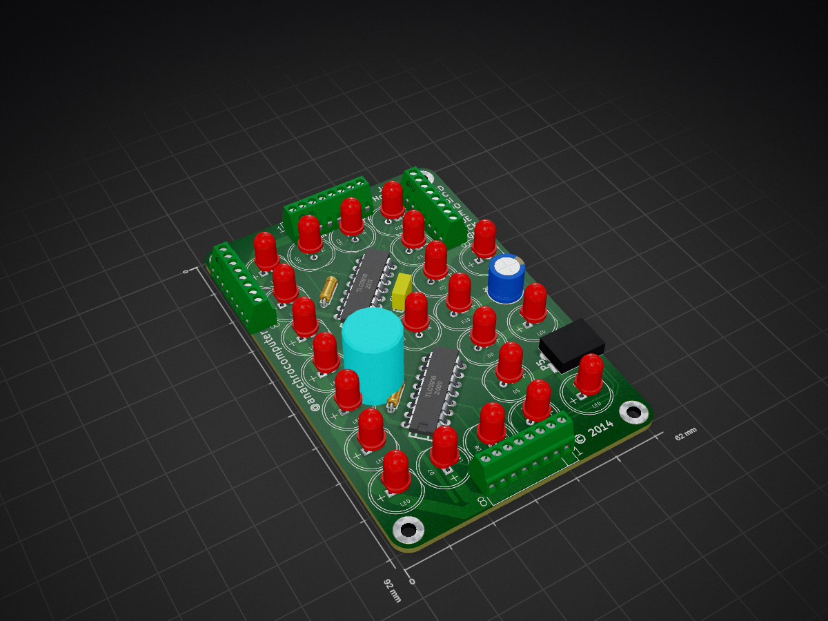
Ledhexdisp is an open-source printed circuit board by anachrocomputer, from the anachrocomputer/LedHex repository on GitHub, published under the GPL-3.0 licence. It is a 2-layer board of 62 × 92 mm with 39 parts on 35 nets, routed with 333 tracks and 27 vias.
It is built around the TLC5916IN. Its parts include 23 diodes, 5 connectors, 3 capacitors, 2 resistors and 2 ICs. It belongs with the lEDs and displays boards of this library.
This repository contains several programs to run on an Arduino and drive a display made from LEDs.
The display was made as a small-volume low-cost PCB using a design drawn in KiCad.
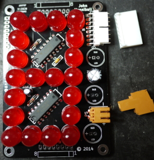
CAD files for the schematic and PCB, designed in 2014 using KiCad V3. This version of KiCad is so old now that it's not practical to update the files. At the time of writing, KiCad is at V8.0.5 and uses a completely different set of PCB footprints from V3. So although it's possible to update the schematic files to use the latest format and the latest symbols, it's difficult to map those symbols to the new footprints. This means that the PCB layout cannot be resynchronised with the schematic. Probably the easiest way to fix this would be to re-draw in KiCad V8.
The schematic is shown as a PDF for reference when writing software to drive the display.
Very simple four-digit clock with flashing colon. So simple, in fact, that there's no way to set the time.
TODO: add a way to set the time.
TODO: add 12/24 hour switch.
TODO: add other types of time display, TBD.
Display a four-digit counter on four LedHex PCBs connected in a chain. Range is 0000-FFFF (0-65535).
Test a four-digit chain of LedHex PCBs by lighting up all the segments in sequence. This is also a test of the LED power supply!
Simply count 0-9, A-F repeatedly on a single digit display.
Test a four-digit chain of LedHex PCBs by lighting up all the segments in sequence.
| Qty | Value | Footprint | References |
|---|---|---|---|
| 23 | LED | LED-10MM | D1, D2, D10, D11, D12, D13, D14, D15, D16, D17, D18, D19, D20, D21, D22, D23 +7 |
| 4 | MHOLE-M3 | , , , | |
| 3 | IN | KK-H-8-notab | P1, P2, P3 |
| 2 | R | R3-LARGE_PADS | R1, R2 |
| 2 | TLC5916 | DIP-16__300_ELL | U1, U2 |
| 1 | 1uF | C1-1 | C1 |
| 1 | 220uF 16V | CP3.5V8D | C3 |
| 1 | 22uF 6.3V | CP1.5V4D | C2 |
| 1 | OUT | KK-V-8-noheader | P4 |
| 1 | VLED | pterm3.5-2 | P5 |
It measures 62 × 92 mm and has 2 copper layers, 1.6 mm thick.
39 parts, built around the TLC5916IN. The full list of its parts is on this page, with links to each part's symbol and footprint where PCBKit's library has them.
From the anachrocomputer/LedHex repository on GitHub, at the commit this page was made from: the board is KiCadV3Pcb/ledhexdisp.kicad_pcb. PCBKit opens the board in the browser, with nothing to install.
Its repository publishes it under the GPL-3.0 licence: you may reuse it on that licence's terms (keep the author's notice, and for a copyleft licence share your changes alike).
411568/Atmega8_FM_radio
Simple FM radio based on Atmega8 and TEA5767 module

javierveras/projectav-telemetry-pdb-2026
Our power distribution and telemetry system's hardware, firmware, and technical documentation.


xx0x/sw63
Sci-fi inspired electronic watch. MK4 currently in the development (out in 2026).

chrisgian05/Digital_LED_clock
A 6-digit 7-segment clock (HH:MM:SS) built around an ATmega328P, an external RTC, and a constant-current LED driver — split across two custom PCBs I designed in KiCad.
