


4 layers33.8 × 46 mm
MorphWatch STM32
deebot/MorphWatch-STM32
The Repo contains KiCAD hardware files and software for Morph Watch
64 parts12

 amwellius/DE2_Project_2021-221
DE2 Project 2021
Water height meter is an open-source printed circuit board by amwellius, from the amwellius/DE2_Project_2021-22 repository on GitHub, published under the MIT licence. It is a 2-layer board with 18 parts on 40 nets.
It is built around the ARDUINO UNO R3, DMG2301L and GPTS203211B. Its parts include 8 resistors, 3 capacitors, 3 connectors, 1 diode and 1 transistor. It belongs with the AVR (ATmega, ATtiny) boards of this library.
2021, Faculty of Electrical Engineering and Communication FEKT

Link to this file in GitHub repository:
https://github.com/amwellius/DE2_Project_2021-22
[blocked]
This simple but useful application will help you to fully control your water tank (not only!) in the garden. Do you want to know how much water is left? Do you want to refill the tank? Or are you interested in controlling your own independent application based on the volume left in the tank?
No problem!
With our Water Tank Controller you will be able to:
[blocked]
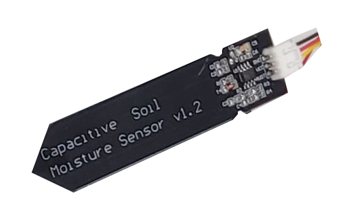
As main programming board Arduino UNO is used. For displaying results Nokia 5110 LCD display was selected, Relay module and button (optional). Ultrasonic HC-SR04 is the primary water level sensor. There is Capacitive Soil Moisture Sensor v1.2 used as backup to prevent overflowing the tank when debris (leaves, flowers, pollen, ...) clogs in the tank sink. By small adjustments in the code it can be transformed into rain detector.
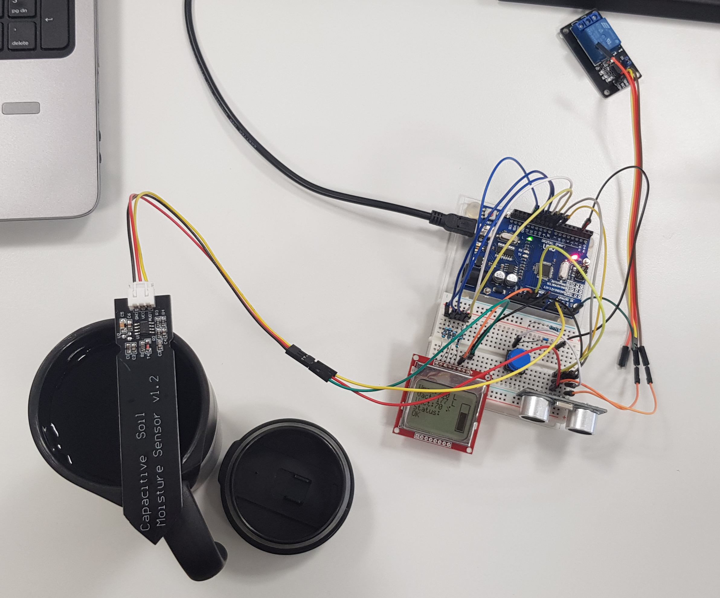
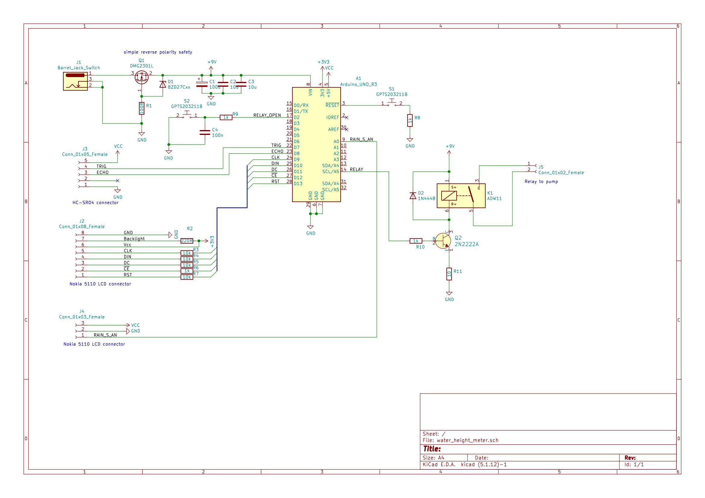
Application uses a number of digital I/O pins, analog input pins and 3.3 V and 5 V power supply. Schematic can be seen here SCHEMATIC.
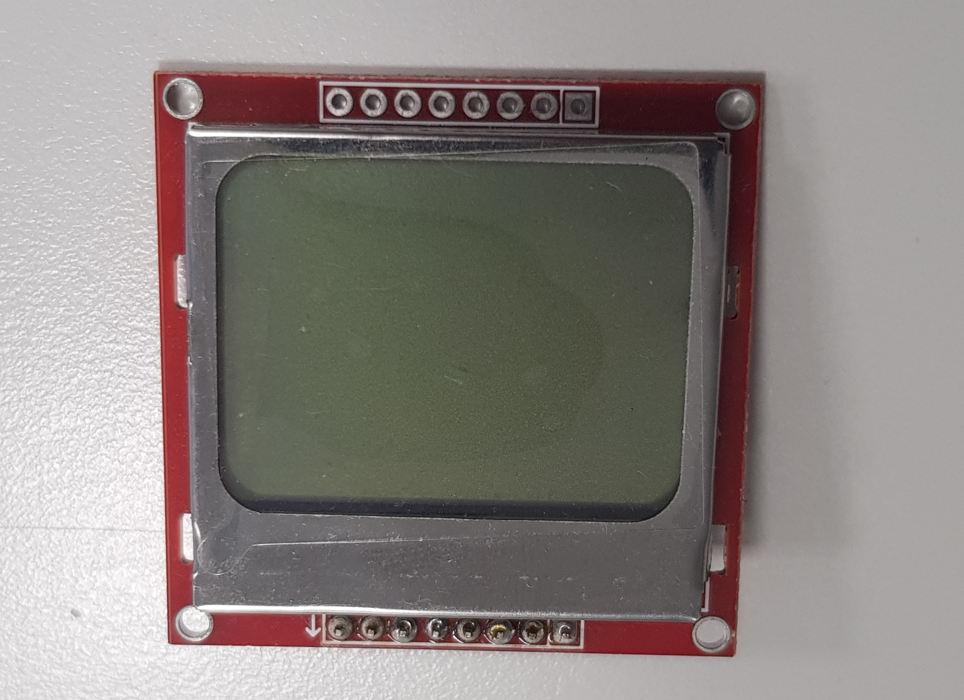
All output data is shown on Nokia LCD display. Third party library has been edited in order to use it with Arduino UNO and image display function was implemented. Display's resolution 84x48 allows to display many useful data or graphic representation of water level as well. Drawn images were converted to byte arrays to simplify the usege in Microchip Studio.
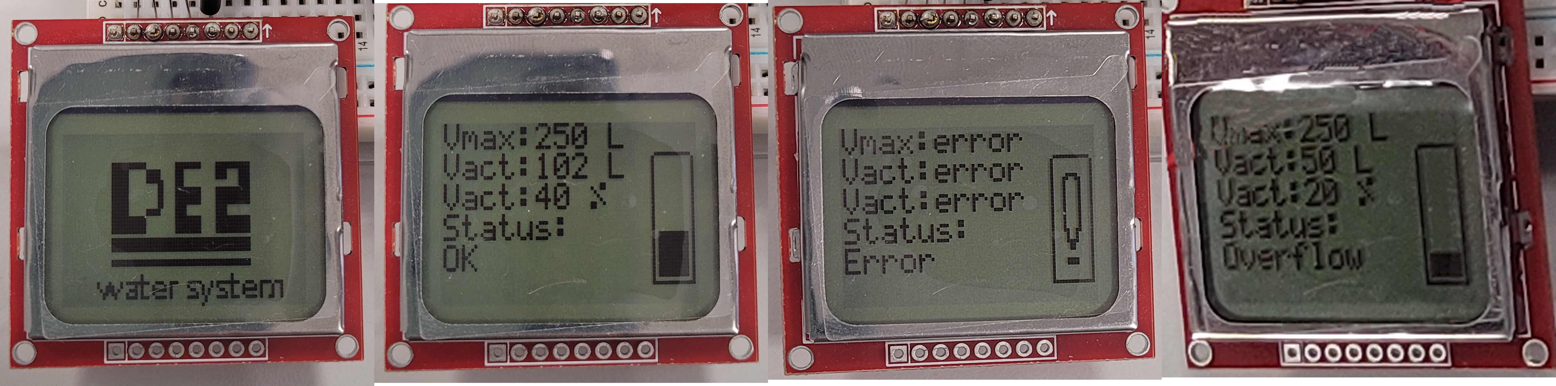
Picture below shows possible states.

Also some resistors had to be used to properly connect LCD to Arduino board.
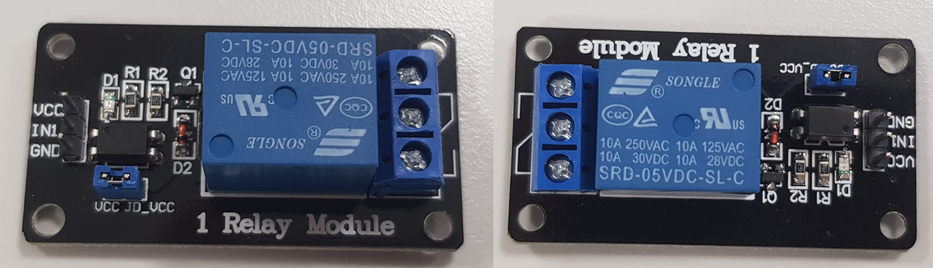
Usage of relay(s) is optional. C code has implemented section which toggles the relay module by pressing button connected to Arduio UNO. It can be connected to pump or solenoid to enable watering plants or other uses of the water. A capacitor inserted in cicruit (as RL low pass filter) helps to stabilize overoscillations generated by the button. By using hardware filter we were able to implement button handling with interrupt.
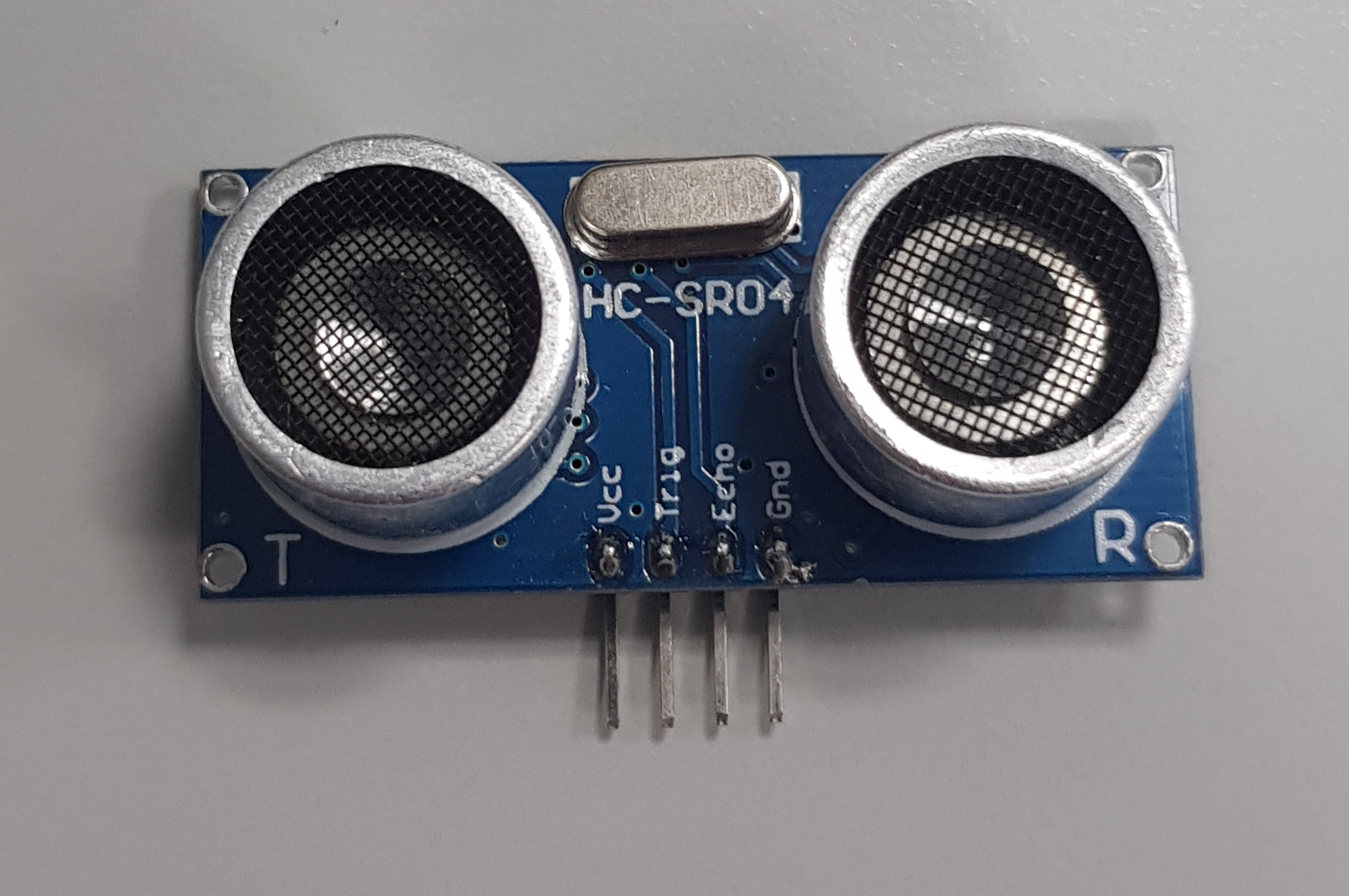
Main sensor for measuring the water level of the tank is HC-SR04. After entering its dimensions the sensor is calibrated. Providing it with short 10us pulse will result in receiving 8 cycles of 40KHz signal. This will be given by ECHO pin, so received value will be the time the wave travelled to the water and back to the sensor. Final distance can be obtained by this equation:

Where t is the received value on ECHO pin and 0.034 cames from the speed of sound (340 m/s = 0.034 m/us). Sound wave travels from sensor to water, but from water to the sensor as well. That is why the result has to be devided by two. Arduino UNO's timers are used to measure width of received square signal. After calculation, distance in milimeters is returned. Its value is sent to other functions, so supplementary data can be sent to display on Nokia LCD.
It is situated a few centimeters above main ultrasonic sensor. If ultrasonic fails, this option will prevent overflowing the water tank. Display will print System overflow message. Relay module can the programmed for specific behavior after getting to overflow stage, too (optional).
Sensor is connected to analog input pin, GND and Vcc=5 V. Its usage describes table below.
| Value | Results in |
|---|---|
| <=850 | System working properly. |
| >850 | System malfunction! |
[blocked]
Code for this application was written in C, compilated using AVR/GNU C compiler and MicroChip Studio. Project consists of several libraries, list of all files can be found below:
main.h- main function header,main.c - includes main procedures and functions,english_font.h - characters for LCD display,nokia_5110_lcd.h - header for LCD display,nokia_5110_lcd.c - functions for LCD controlling,water_symbols.h - header for c file,water_symbols.c - byte maps (figures on LCD),gpio.h - input/output header,gpio.c - input/output functions,timer.h - header for timers in Arduino UNO,HC-SR04.h - header for ultrasonic sensor,HC-SR04.c - definitions for ultrasonic sensor.All files are available here:
main.h, main.c, english_font.h, nokia_5110_lcd.h, nokia_5110_lcd.c, water_symbols.h, water_symbols.c, gpio.h, gpio.c, timer.h, HC-SR04.h, HC-SR04.c.
Some important parts of codes will be discuss.
main.cExample of controlling graphic representation of water level.
if (percentage == 100) selector = 10;
if (selector == 0) {
    LCD_write_bytes_xy_defined_width((unsigned char*)water_level_default, 14, 70, bucket_x, bucket_y);
} else {
    LCD_write_bytes_xy_defined_width((unsigned char*)all_water_states[selector], 14, 70, bucket_x, bucket_y);
}

// display maximum

itoa(tank_volume, distance_str, 10);
LCD_write_english_string(0, 0, "Vmax:");
LCD_write_english_string_continue(distance_str);
LCD_write_english_string_continue(" L");nokia_5110_lcd.hFunctions used to control LCD Nokia Display.
void LCD_clear();
void LCD_init();
void LCD_write_byte(unsigned char dat, unsigned char command);
void LCD_write_english_string(unsigned char X,unsigned char Y,char *s);
void LCD_write_english_string_continue(char *s);
void LCD_write_english_string_continue_precise(char *s, uint16_t data_len);
void LCD_write_char(unsigned char c);
void LCD_set_XY(unsigned char X, unsigned char Y);
void LCD_write_init();
void LCD_write_whole_screen(unsigned char *cells, uint16_t cells_n, uint16_t start_x, uint16_t start_y);
void LCD_write_bytes_xy_defined_width(unsigned char *cells, uint16_t width, uint16_t size, uint16_t x, uint16_t y);water_symbols.cExample of byte map (icon of 70% left).
const unsigned char water_level_70[] = {
    // 'water level 70%', 14x35px

    0xfe, 0x01, 0x01, 0x01, 0x01, 0x01, 0x01, 0x01, 0x01, 0x01, 0x01, 0x01, 0x01, 0xfe, 0xff, 0x00,
    0xf8, 0xf8, 0xf8, 0xf8, 0xf8, 0xf8, 0xf8, 0xf8, 0xf8, 0xf8, 0x00, 0xff, 0xff, 0x00, 0xff, 0xff,
    0xff, 0xff, 0xff, 0xff, 0xff, 0xff, 0xff, 0xff, 0x00, 0xff, 0xff, 0x00, 0xff, 0xff, 0xff, 0xff,
    0xff, 0xff, 0xff, 0xff, 0xff, 0xff, 0x00, 0xff, 0x07, 0x04, 0x05, 0x05, 0x05, 0x05, 0x05, 0x05,
    0x05, 0x05, 0x05, 0x05, 0x04, 0x07
};HC-SR04.cCalculation of water level distance.
TCCR1B |= (1 << ICES1);                                             // Reset to rising edge

        falling = ICR1;                                             // Read value ticks

        counts = falling - rising;                                  // Calc. difference between start and stop of the pulse

        dist = ((US_PER_COUNT * (uint32_t)counts) * 340) / 2000;    // Distance in mm


        for (int8_t i = 9; i >= 1; i--) {
            dist_vals[i] = dist_vals[i-1];
        }
        dist_vals[0] = dist;
[blocked]
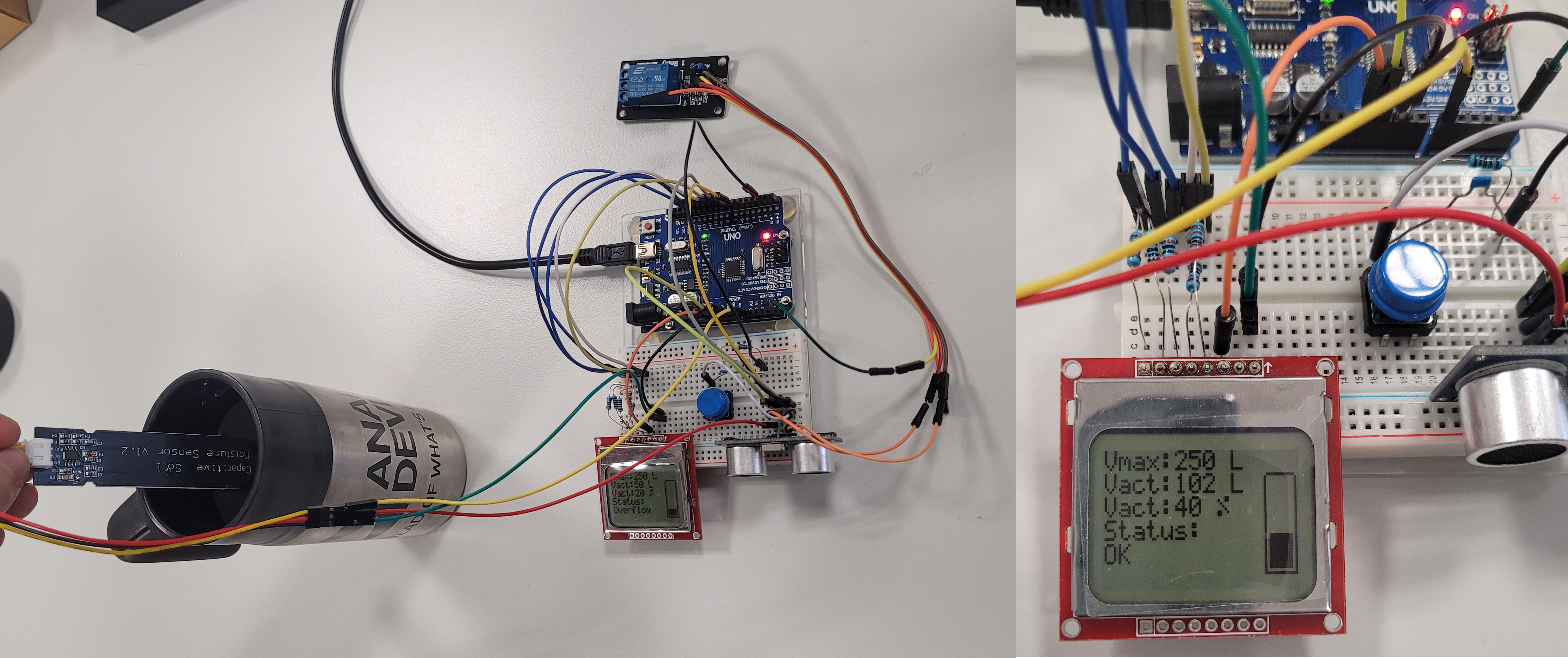
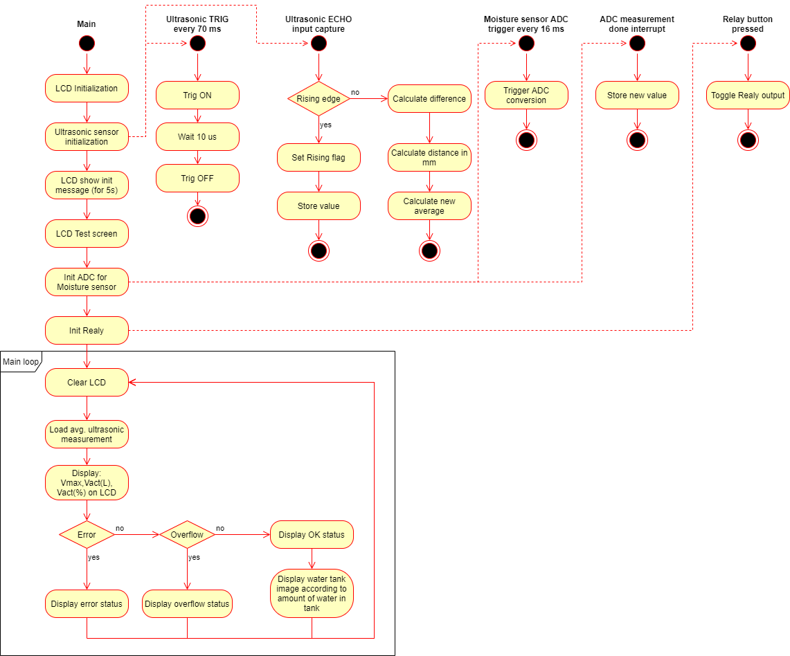
The main purpose of this application is to automatize operation of regulating water level in specified tank. After knowing volume of owned tank, ultrasonic sensor connected to Arduino UNO board will measure the water level. LCD Nokia 5110 display shows water level in centimeters, percentage and maximum usable volume of the water-tank. Application uses one extra sensor to control the maximum volume. It is situated few centimeters above the max bound of water (we do not want to fill the tank completely to prevent owerflow). If the water reaches this sensor LCD shows problem (Owerflow, Error) depending on the value of ultrasonic sensor.
Our product has the ability to interact with relay modules for external usage. These can be used to replenish the tank, irrigation pump control, DC fans, windows opening, and others.
Mount Ultrasonic sensor on the top of water tank. Sensor's reference zero (100%) is set to be 4 centimeters from the ultrasonic transceiver.
Mount Capacitive sensor about 1 centimeter above max water height. (If ultrasonic fails, capacitive sensor will save it from drowning).
Insert dimensions of your water tank into C code. If maximum height of your tank is e.g. 100 cm, than insert only 96 cm, to prevent owerflow.
// Tank Volume

//**Enter values in cm !

#define TANK_X  ((uint32_t)80)
#define TANK_Y  ((uint32_t)80)
#define TANK_Z  ((uint32_t)96)
Application is now set up. The Nokia LCD screen provides needed information according figure below. User can see data as
Vmax:800 L,Vact:441 L,Vact:55 %,OK, ERROR, OVERFLOW.
Relay module is set to interact with pressing installed button. Do not hesitate to use your creativity and relay module (modules) on your own by simply editing the code.
After powering on, test screen procedure runs (represented by DE2 Water System screen and graphic tank icon filling up). System is ready to operate!
Level of water in tank is between 0 and 100%, capacitive sensor is not activated by water reaching its level; system working correctly.
Rises when unexpected data is measured.
Ultrasonic sensor occurred problem. Water reaches capacitive sensor. Different data received from two sensors leads to system Overflow stage message.
[blocked]
Video available here:
Link to YouTube
HEX file available here:
HEX file
Documentation available here:
As PDF file
or as doxygen generated website (download required, open index.html)
[blocked]
All pictures have been taken in DE2 Laboratories!
©2021, VUT FEKT, Brno, Czech Republic
Košík, Karetka, Kocum, Knob
For Educational Purposes Only!
| Qty | Value | Footprint | References |
|---|---|---|---|
| 4 | 10k | Resistor_SMD:R_0603_1608Metric_Pad1.05x0.95mm_HandSolder | R3, R4, R5, R7 |
| 2 | 1k | Resistor_SMD:R_0603_1608Metric_Pad1.05x0.95mm_HandSolder | R6, R8 |
| 2 | C | Capacitor_SMD:C_0805_2012Metric_Pad1.18x1.45mm_HandSolder | C2, C3 |
| 1 | 100R | Resistor_SMD:R_1206_3216Metric_Pad1.42x1.75mm_HandSolder | R1 |
| 1 | 220R | Resistor_SMD:R_0603_1608Metric_Pad1.05x0.95mm_HandSolder | R2 |
| 1 | Arduino_UNO_R3 | Module:Arduino_UNO_R3 | A1 |
| 1 | BZD27Cxx | Diode_SMD:D_SMF | D1 |
| 1 | Barrel_Jack_Switch | Connector_BarrelJack:BarrelJack_Wuerth_6941xx301002 | J1 |
| 1 | CP | Capacitor_THT:CP_Radial_D6.3mm_P2.50mm | C1 |
| 1 | Conn_01x05_Female | Connector_PinHeader_2.54mm:PinHeader_1x05_P2.54mm_Vertical | J3 |
| 1 | Conn_01x08_Female | Connector_PinHeader_2.54mm:PinHeader_1x08_P2.54mm_Vertical | J2 |
| 1 | DMG2301L | Package_TO_SOT_SMD:SOT-23 | Q1 |
| 1 | GPTS203211B | digikey-footprints:PushButton_12x12mm_THT_GPTS203211B | S1 |
deebot/MorphWatch-STM32
The Repo contains KiCAD hardware files and software for Morph Watch

halworsen/tdt4295-grafikk
Bugge is an embedded system designed from absolute scratch, and is capable of drawing arbitrarily complex 3D wireframe models with VGA output.

micromouseuci/micromouse-kit
This is the official GitHub of Micromouse @ UCI. This repository is here to allow you to build your own mouse for competition.


constancegdl/RP2350-FI-Attack-PCB
PCB designed for fault injection on the RP2350.

harshsahu32672/STM32-DEVLOPMENT-BOARD
A fully custom-designed STM32L433CBT6 development board built using KiCad, featuring USB connectivity, debugging support, and optimized PCB layout for embedded applications.

JamesM92/ScareBanger
PCB for controlling relay baords and workign with octobanger software
18 parts, built around the ARDUINO UNO R3, DMG2301L and GPTS203211B. The full list of its parts is on this page, with links to each part's symbol and footprint where PCBKit's library has them.
From the amwellius/DE2_Project_2021-22 repository on GitHub, at the commit this page was made from: the board is PCB_project/water_height_meter.kicad_pcb. PCBKit opens the board in the browser, with nothing to install.
Its repository publishes it under the MIT licence: you may reuse it on that licence's terms (keep the author's notice, and for a copyleft licence share your changes alike).