2 layers220.1 × 98 mm
 amnxlab/Void-SmartBot
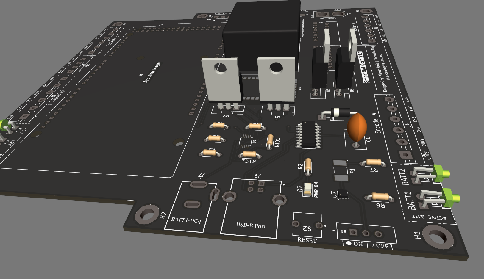
A professionally engineered 4-layer Control PCB for mobile robotics and embedded systems.
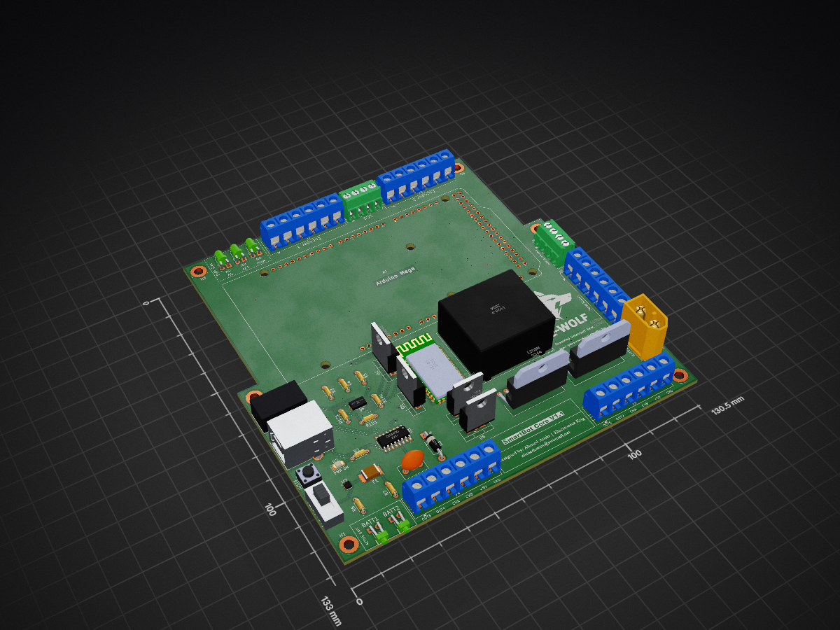
PCB Board is an open-source printed circuit board by amnxlab, from the amnxlab/Void-SmartBot repository on GitHub. It is a 4-layer board of 130.5 × 133 mm with 48 parts on 158 nets, routed with 834 tracks and 81 vias.
It is built around the CH340C, HC-05 and L298N, with the LV25-P, TVS1800DRV and IRF4905 among its other parts. Its parts include 10 connectors, 9 resistors, 9 ICs, 7 diodes and 2 transistors.


A professionally engineered 4-layer PCB for mobile robotics and embedded systems.
SmartBot Core V1.1 is a custom-designed control board tailored for mobile robotics platforms.
Built on a 4-layer FR4 stack, it combines reliable power management, motor control, encoder support, and clean communication — all in a compact, Arduino Mega-compatible footprint.
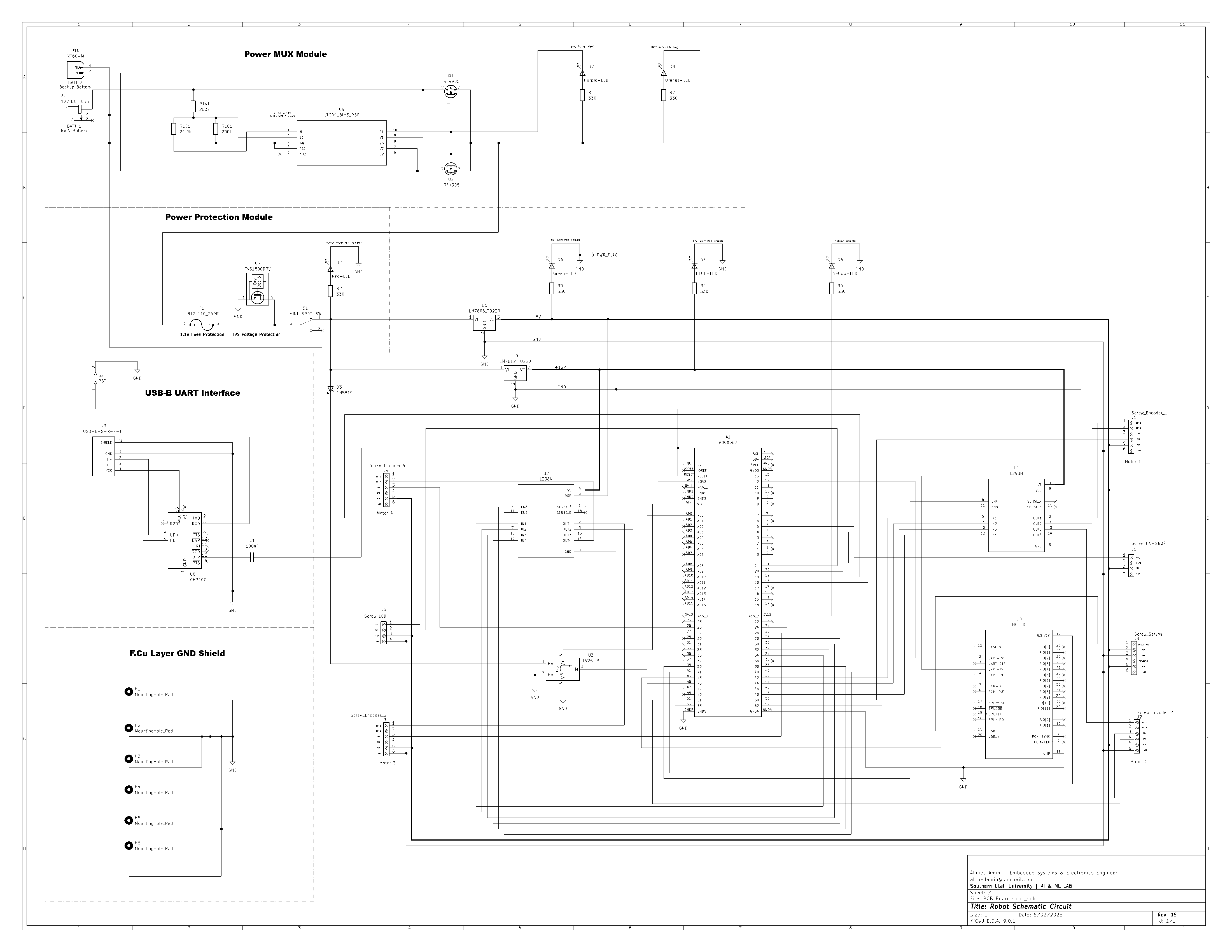
Schematic
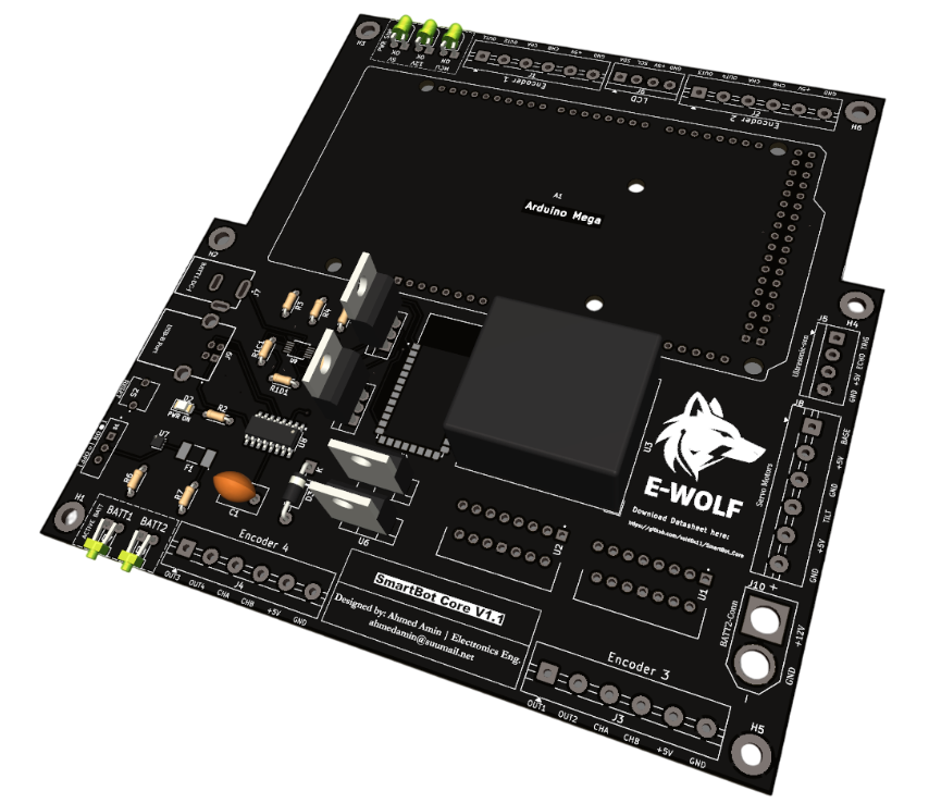
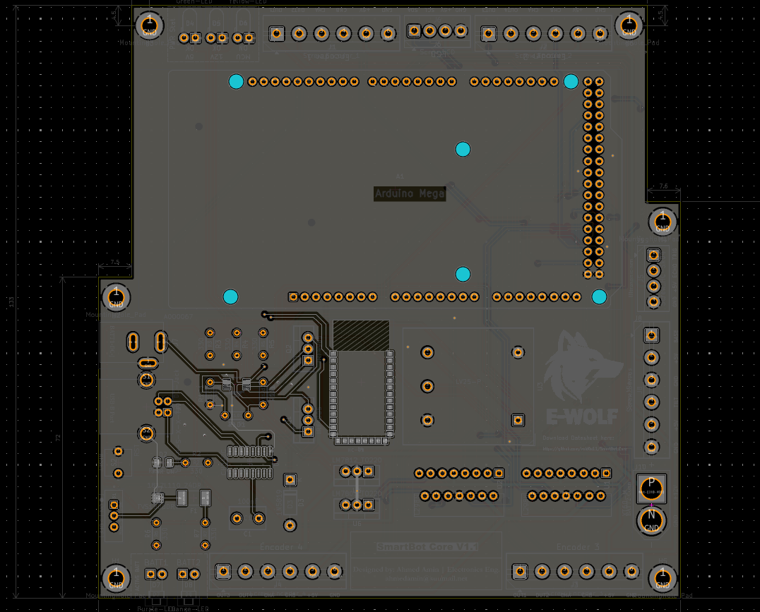
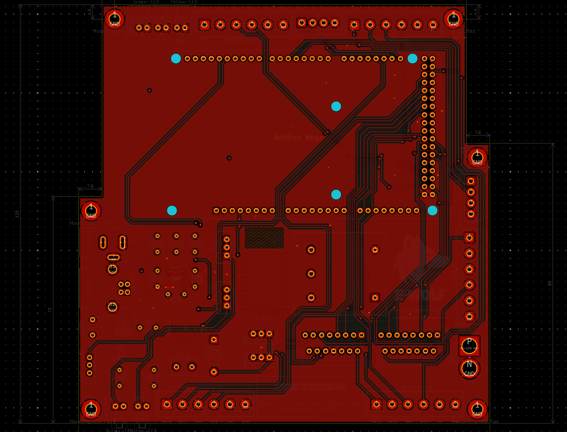
Layer 1 (Surface Mount)
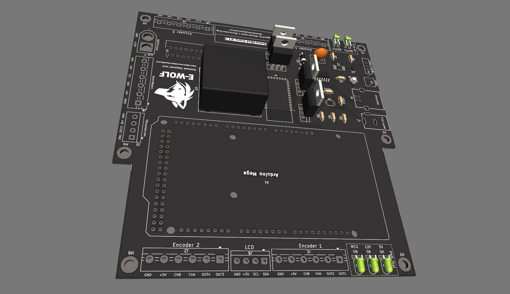
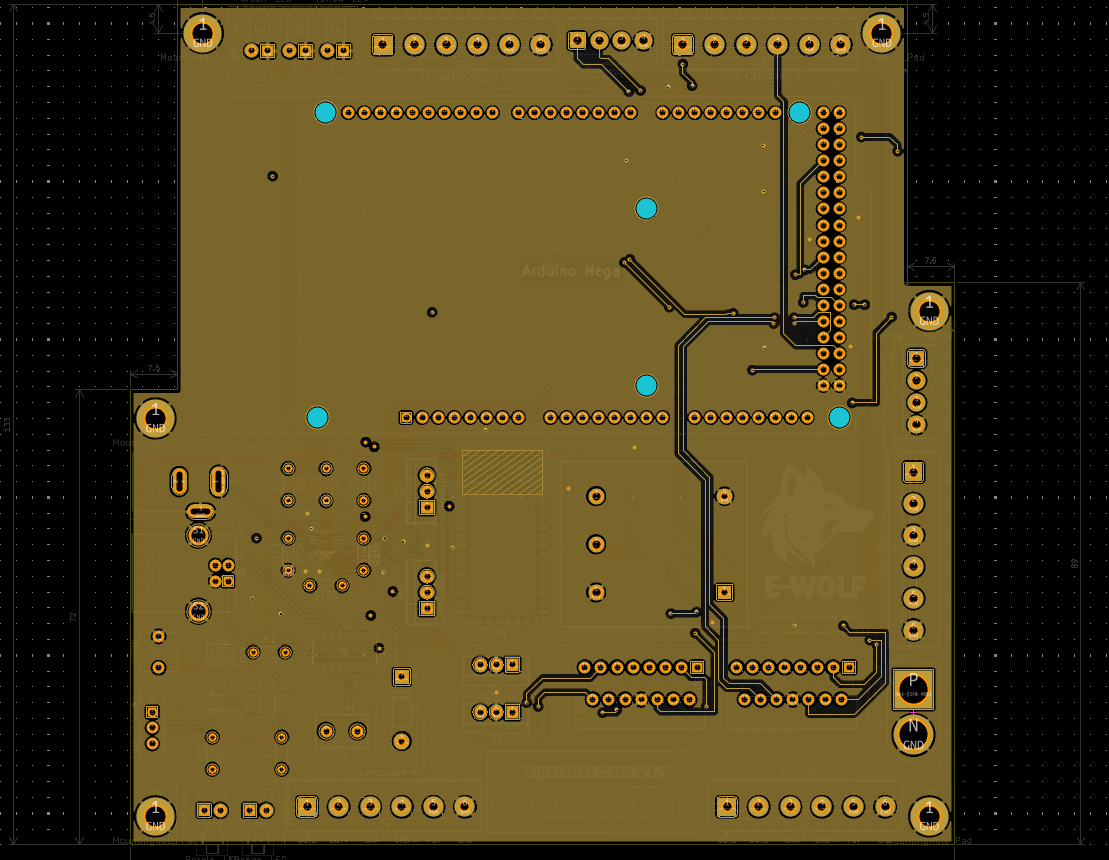
Layer 2 (Light Signals, GND Refrence)
Layer 3 (Power Plane)
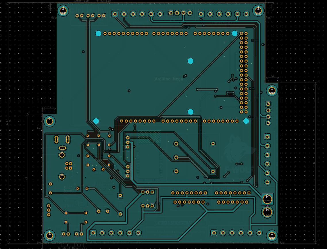
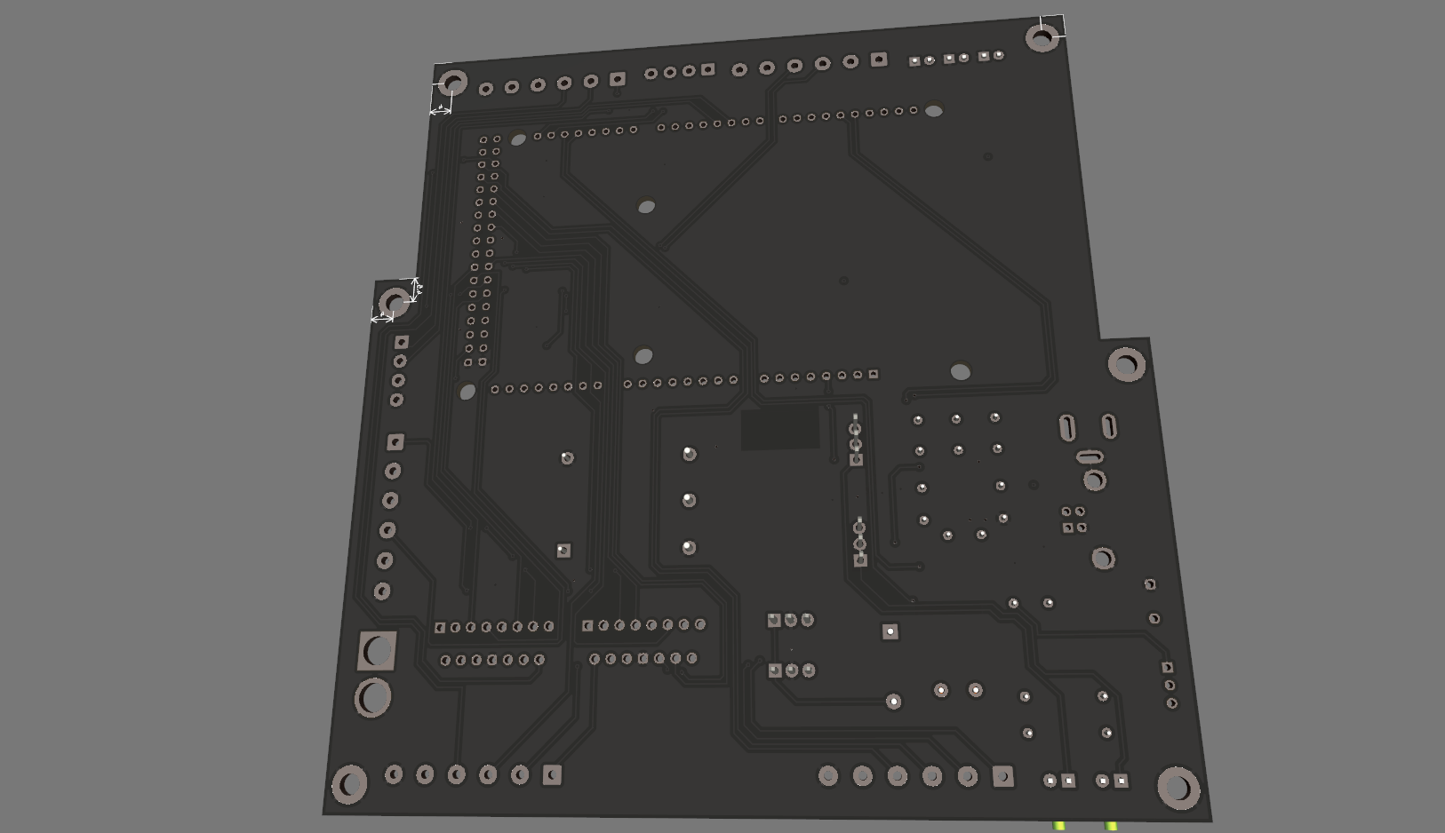
Layer 4 (Main Traces)
| Qty | Value | Footprint | References |
|---|---|---|---|
| 6 | 330 | Resistor_THT:R_Axial_DIN0204_L3.6mm_D1.6mm_P5.08mm_Horizontal | R2, R3, R4, R5, R6, R7 |
| 6 | MountingHole_Pad | MountingHole:MountingHole_3.2mm_M3_ISO7380_Pad | H1, H2, H3, H4, H5, H6 |
| 2 | IRF4905 | Package_TO_SOT_THT:TO-220-3_Vertical | Q1, Q2 |
| 2 | L298N | MyParts:TO127P2020X500X2100-15 | U1, U2 |
| 1 | 100nF | Capacitor_THT:C_Disc_D8.0mm_W5.0mm_P5.00mm | C1 |
| 1 | 12V DC-Jack | MyParts:GCT_DCJ200-10-A-XX-K_REVA | J7 |
| 1 | 1812L110_24DR | MyParts:FUSM4632X200N | F1 |
| 1 | 1N5819 | Diode_THT:D_DO-41_SOD81_P10.16mm_Horizontal | D3 |
| 1 | 200k | Resistor_THT:R_Axial_DIN0204_L3.6mm_D1.6mm_P5.08mm_Horizontal | R1A1 |
| 1 | 230k | Resistor_THT:R_Axial_DIN0204_L3.6mm_D1.6mm_P5.08mm_Horizontal | R1C1 |
| 1 | 24.9k | Resistor_THT:R_Axial_DIN0204_L3.6mm_D1.6mm_P5.08mm_Horizontal | R1D1 |
| 1 | A000067 | MyParts:MODULE_A000067 | A1 |
| 1 | BLUE-LED | LED_THT:LED_D3.0mm_Horizontal_O1.27mm_Z2.0mm | D5 |
| 1 | CH340C | Package_SO:SOIC-16_3.9x9.9mm_P1.27mm | U8 |
| 1 | Green-LED | LED_THT:LED_D3.0mm_Horizontal_O1.27mm_Z2.0mm | D4 |
| 1 | HC-05 | MyParts:XCVR_HC-05 | U4 |
| 1 | LM7805_TO220 | Package_TO_SOT_THT:TO-220-3_Vertical | U6 |
| 1 | LM7812_TO220 | Package_TO_SOT_THT:TO-220-3_Vertical | U5 |
| 1 | LTC4416IMS_PBF | MyParts:MSOP-10_MS | U9 |
| 1 | LV25-P | Sensor_Voltage:LEM_LV25-P | U3 |
| 1 | MINI-SPDT-SW | MyParts:SW_MINI-SPDT-SW | S1 |
| 1 | Orange-LED | LED_THT:LED_D1.8mm_W1.8mm_H2.4mm_Horizontal_O3.81mm_Z1.6mm | D8 |
| 1 | Purple-LED | LED_THT:LED_D1.8mm_W1.8mm_H2.4mm_Horizontal_O3.81mm_Z1.6mm | D7 |
| 1 | RST | MyParts:SW_BUTT-2 | S2 |
| 1 | Red-LED | LED_SMD:LED_1206_3216Metric | D2 |
| 1 | Screw_Encoder_1 | TerminalBlock:TerminalBlock_MaiXu_MX126-5.0-06P_1x06_P5.00mm | J1 |
| 1 | Screw_Encoder_2 | TerminalBlock:TerminalBlock_MaiXu_MX126-5.0-06P_1x06_P5.00mm | J2 |
| 1 | Screw_Encoder_3 | TerminalBlock:TerminalBlock_MaiXu_MX126-5.0-06P_1x06_P5.00mm | J3 |
| 1 | Screw_Encoder_4 | TerminalBlock:TerminalBlock_MaiXu_MX126-5.0-06P_1x06_P5.00mm | J4 |
| 1 | Screw_HC-SR04 | TerminalBlock_4Ucon:TerminalBlock_4Ucon_1x04_P3.50mm_Horizontal | J5 |
| 1 | Screw_LCD | TerminalBlock_4Ucon:TerminalBlock_4Ucon_1x04_P3.50mm_Horizontal | J6 |
| 1 | Screw_Servos | TerminalBlock:TerminalBlock_MaiXu_MX126-5.0-06P_1x06_P5.00mm | J8 |
| 1 | TVS1800DRV | Package_SON:WSON-6-1EP_2x2mm_P0.65mm_EP1x1.6mm | U7 |
| 1 | USB-B-S-X-X-TH | MyParts:SAMTEC_USB-B-S-X-X-TH | J9 |
| 1 | XT60-M | MyParts:AMASS_XT60-M | J10 |
| 1 | Yellow-LED | LED_THT:LED_D3.0mm_Horizontal_O1.27mm_Z2.0mm | D6 |
It measures 130.5 × 133 mm and has 4 copper layers, 1.6 mm thick.
48 parts, built around the CH340C, HC-05, L298N and LV25-P. The full list of its parts is on this page, with links to each part's symbol and footprint where PCBKit's library has them.
From the amnxlab/Void-SmartBot repository on GitHub, at the commit this page was made from: the board is Board Files/PCB Board.kicad_pcb and its schematic Board Files/PCB Board.kicad_sch. PCBKit opens the board in the browser, with nothing to install.
Its repository states no licence, so its author keeps all rights: ask amnxlab before reusing the design.


AdvikChitre/MSL_Imperial_2023
Repository for Imperial College London Robocup MSL team 2023


misko/prompt2device
The separate vNext PCB skill and orchestrator package is available alongside the reference workflow below; existing projects keep their accepted toolchain until an explicit migration.

gamantaray-2026/Electronic-Control-System-ASV-Gamantaray-2026
Dokumentasi teknis, skematik PCB, manajemen daya, arsitektur sistem kontrol, dan arsitektur sistem komunikasi untuk Autonomous Surface Vehicle (ASV) Gamantaray Safinah One 2026

Rami-Troudi/Electrique-Eurobot-IEEE-INSAT-2026
Repo for my electrical work for the Eurobot competition