4 layers40 × 60 mm
Trinketcore
alph4345/test
TrinketCore puts everything a small rechargeable gadget needs on one 40 × 60 mm board, ready to order assembled from PCBWay:
113 parts

 alph4345/test
TrinketCore puts everything a small rechargeable gadget needs on one 40 × 60 mm board, ready to order assembled from PCBWay:
Capcore is an open-source printed circuit board by alph4345, from the alph4345/test repository on GitHub. It is a 4-layer board of 21 × 48 mm with 68 parts on 43 nets, routed with 462 tracks and 67 vias.
It is built around the TPS63031DSKR, PCF8563T/5 and TPS3808G01DBVR-TP, with the USBLC6-2SC6, AO3400A and 1N4148WS among its other parts. Its parts include 28 resistors, 14 capacitors, 8 transistors, 5 ICs and 4 diodes.


TrinketCore puts everything a small rechargeable gadget needs on one 40 × 60 mm board, ready to order assembled from PCBWay:
The power side is CapCore's proven circuit. It cuts off before the capacitor over-discharges, uses a soft power switch that turns the whole board off, and has a buck-boost converter that keeps 3.3 V steady as the capacitor drains.
| Top | Bottom (capacitor bay) |
|---|---|
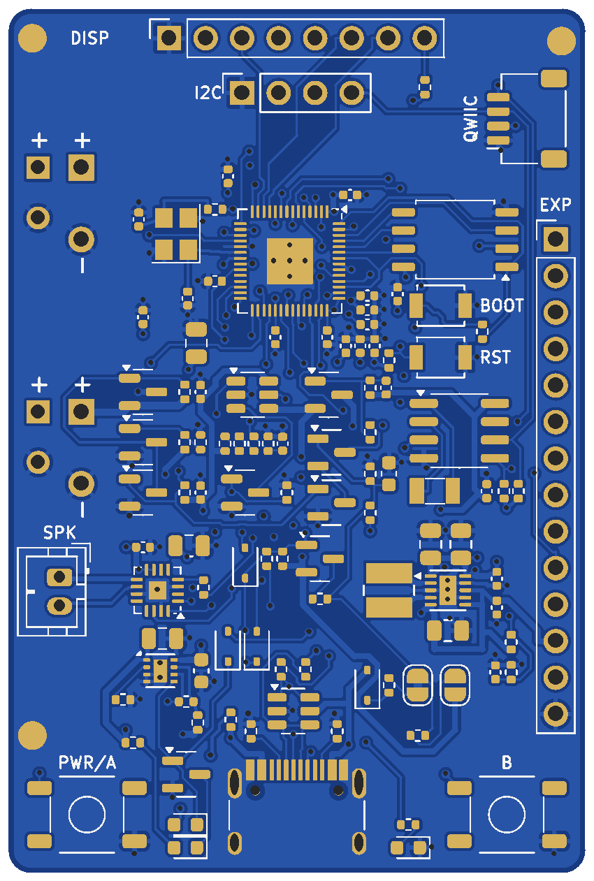 | 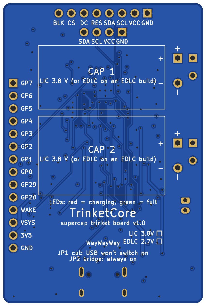 |
Renders of the actual Gerber layers. The display plugs into the socket along the top edge. The capacitors solder into the pads on the left and lie flat inside the outlines on the back.
| Capacitors | BT1 + BT2 in parallel: one or two 3.8 V lithium-ion capacitors (LIC). EDLC build: 2.7 V supercapacitors |
| Charging | USB-C, TI BQ25173, 300 mA: two 220 F capacitors fill in about 30 minutes. Red LED (CHG) while charging, green LED (FULL) when full (USB plugged in) |
| Protection | disconnects at 2.61 V (LIC) / 1.96 V (EDLC) and stays off until USB returns; ship mode for storage |
| Power switch | the whole board is off between uses (about 5 µA). It turns on from button A, a lid/tilt switch on WAKE, the clock alarm, or USB. Firmware keeps it on with HOLD |
| 3.3 V | TI TPS63031 buck-boost, ~500 mA even from a nearly empty capacitor |
| Microcontroller | Raspberry Pi RP2040, 12 MHz crystal, 16 MB Winbond flash, USB-C data for programming, BOOT and RESET buttons (SWD is not broken out: the USB bootloader is in ROM) |
| Display | J4: socket for SPI TFT/OLED modules (GND VCC SCL SDA RES DC CS BLK), backlight dimmable by PWM. J5: 4-pin I²C OLED socket. J8: Qwiic/STEMMA QT |
| Charge reading | capacitor voltage on an ADC pin, plus "charging" and "USB present" inputs |
| Sound | MAX98357A I²S class-D amplifier, 9 dB gain, shut down when idle; J7 speaker connector (JST PH 2.0 or solder the wires) |
| Clock | NXP PCF8563 real-time clock: wakes the board on a timer or alarm (virtual pets, e-ink updates) |
| Buttons | A / POWER (turns the board on and is readable by firmware), B, BOOT, RESET |
| LEDs | red CHG, green FULL (charging), blue user LED on GP25 |
| Expansion | J6, 14 pins: GP0–GP7, GP28–GP29 (analog), WAKE, VSYS, 3V3, GND |
| Board | 4 layers, 40 × 60 × 1.6 mm, all parts on top, PCBWay standard rules (6/6 mil, 0.3 mm holes) |
The socket fits the common 0.96–1.54″ modules, so you can try several and pick per product. A screen is the second-biggest power draw after a speaker, so the firmware uses it in short bursts: wake, show, dim, switch off.
| Display | Colour | Draw (with the RP2040 running) | Good for |
|---|---|---|---|
| 0.96″ SSD1306 OLED, 128 × 64 (SPI on J4 or I²C on J5) | mono | ~35–40 mA; dark screens use less | games, menus, pets |
| 1.3–1.54″ ST7789 IPS TFT, 240 × 240 | full colour | ~45 mA at 60 % backlight, ~30 mA dimmed | colour animations, charms, games |
| 1.28″ GC9A01 round TFT, 240 × 240 | full colour | about the same as the ST7789 | keychain "digital charms" |
| 1.54″ 200 × 200 or 3.7″ 480 × 280 e-paper module (SSD1681 and similar) | black/white, 4 greys, or black/white/red | nothing between refreshes; ~30 mA for 2–3 s per black/white refresh (~14 s for three-colour) | tarot oracles, badges, pets, clocks: always visible |
Yes, colour TFTs work well. The backlight is most of the extra power, so dim it and switch off after a few seconds. On two 220 F capacitors a colour charm shown for 10 s, 30 times a day, lasts about four weeks. Played continuously, a colour game lasts about two hours. See the design method for the numbers.
Module pin orders vary. Modules labelled GND VCC SCL SDA RES DC CS BLK plug
straight into J4. Seven-pin OLEDs (GND VCC D0 D1 RES DC CS) use the first
seven positions. Others, including many GC9A01 modules (VCC GND ...), need
short jumper wires. Check that GND and VCC line up before plugging in.
E-ink works too, and suits anything that should stay visible: the image costs no power at all once drawn, so the board can switch fully off. E-paper modules have a BUSY output where TFTs have a backlight input. Wire them to J4 by function (VCC → 3V3, GND, DIN → MOSI, CLK → SCK, CS, DC, RST → RES) with BUSY on the BLK pin, which the RP2040 reads on GP13. The oracle example shows a random tarot card this way.
LIC build, 85 % converter efficiency, 5 µA standby
(tools/energy_calc.py):
| Trinket | 1 × 120 F | 1 × 220 F | 2 × 220 F |
|---|---|---|---|
| Music box: 20 s tune + LEDs (~70 mA), 10 plays a day | 75 plays (8 days) | 138 plays (14 days) | 276 plays (4 weeks) |
| Colour TFT charm: 10 s shows (45 mA), 30 a day | 8 days | 14 days | 4 weeks |
| Virtual pet on e-paper: wakes every 30 min (30 mA × 3 s) | 3 weeks | 6 weeks | 3 months* |
| Tarot oracle on e-paper: a card per press (30 mA × 5 s), 10 a day | 600 draws (2 months) | 1,100 draws* | 2,200 draws* |
| OLED game, continuous (40 mA) | 45 min | 80 min | 2.7 h |
| Colour TFT game, continuous (55 mA) | 33 min | 60 min | 2 h |
* Beyond a month or two the capacitors' own self-discharge dominates.
The two capacitor positions sit along the left edge. Square pad = +. Each
position takes a 5.0 mm lead pitch (10–12.5 mm cans) or 3.5 mm (8 mm cans).
Bend 16 mm cans' 7.5 mm leads in slightly. Bend the leads 90° so each can lies
flat on the back inside its outline (CAP 1, CAP 2), with its leads at the
left edge. Stick a strip of Kapton tape under each can, and glue or strap
large cans.
Never fit a 2.7 V supercapacitor to a board built with the LIC values. It would be charged to 3.71 V and can vent. Tick the build box on the back, and measure the charge voltage before fitting capacitors (see Bring-up).
J4 display socket (top edge, pin 1 = square pad, left): GND · 3V3 · SCK (GP10) · MOSI (GP11) · RES (GP12) · DC (GP9) · CS (GP8) · BLK (GP13 via 100 Ω)
J5 I²C OLED socket: GND · 3V3 · SCL (GP17) · SDA (GP16). J8 Qwiic: GND · 3V3 · SDA · SCL. The same bus as the clock (address 0x51), with 4.7 kΩ pull-ups.
J6 expansion (right edge, pin 1 at the top): GP7 · GP6 · GP5 · GP4 · GP3 · GP2 · GP1 · GP0 · GP29 · GP28 · WAKE · VSYS · 3V3 · GND. The order matches the RP2040's pins, which keeps the tracks from crossing; the back silkscreen labels every pin.
WAKE: pull to GND to switch the board on (lid, tilt, reed or vibration
switch). For a lid that may stay open, put a 1 µF capacitor in series
with the switch and a 22 MΩ resistor across that capacitor. Opening the
lid then sends one wake pulse, and the board can still switch itself off.VSYS: the capacitor voltage (2.6–3.7 V), on only while the board runs.
Use it for vibration motors or LED strips that tolerate it.J7 speaker: 8 Ω, 0.5–1 W. GPIO map: see the firmware README.
| LED | Meaning |
|---|---|
| red CHG | charging |
| green FULL | USB plugged in and the capacitors are full |
| red and green blinking alternately | charger fault (for example a capacitor wired backwards, or overheating) |
| blue | yours (GP25) |
With USB plugged in the board also switches on, so a gauge can show charging progress. Cut jumper JP1 on the back if plugging in should only charge. Bridge JP2 for gadgets without a power button (always on above the cut-off).
| State | Drain from the capacitors | Leaves the state when… |
|---|---|---|
| Running | your load ÷ ~85 % | firmware drops HOLD |
| Off | ~5 µA (clock running) | button A, WAKE, clock alarm/timer, USB |
| Cut-off / ship mode | leakage only | USB is plugged in |
Everything is in fab/:
| File | Upload / use |
|---|---|
trinketcore-gerbers.zip | the PCB (Gerbers + drill) |
pcbway-bom-lic.csv (or -edlc.csv) | assembly BOM for your build |
pcbway-centroid.csv | pick-and-place positions (mm, origin at the bottom-left corner, same as the Gerbers) |
trinketcore-assembly-top.pdf, -back.pdf | assembly drawings, if PCBWay asks |
parts-list.csv | every part, including the ones you fit yourself |
trinketcore-gerbers.zip. It should read 40 × 60 mm and 4 layers.WayWayWay placeholder where PCBWay can
print it. Tell them in the notes, or pick the remove-order-number option.pcbway-bom-lic.csv and pcbway-centroid.csv.Rough cost (prices change, so trust the quote): about US$25–50 for five 4-layer boards, plus assembly (setup ~US$30–50, parts ~US$8–12 per board with the RP2040, flash and amplifier). Five assembled boards typically land around US$100–180 before shipping. Most of that is fixed, so ten cost little more.
The same files work at other assembly houses (the BOM has manufacturer part numbers, and LCSC numbers where known).
Before fitting the capacitors:
RPI-RP2 drive (blank flash starts the
bootloader). Install CircuitPython and try the
charge gauge with a display on J4.Then unplug USB, fit the capacitors (square pad = +), and plug USB back
in: red while charging, green when full. Unplug and press A: the board runs
for about 5 s, or longer if firmware raises HOLD. A new capacitor that
arrives below the cut-off keeps the board off until it has charged past it.
| File | |
|---|---|
trinketcore.kicad_pro/.kicad_sch/.kicad_pcb | KiCad 7 project |
trinketcore-schematic.pdf | schematic |
TrinketCore.kicad_sym, TrinketCore.pretty/ | project symbols and footprints |
trinketcore.ses | autorouter result that route_pcb.py rebuilds the board from |
scripts/ | the generators |
As with CapCore, the board is generated from code:
cd hardware/trinketcore/scripts
python3 gen_footprints.py
python3 gen_schematic.py && python3 check_netlist.py
python3 check_place.py
FREEROUTING_JAR=/path/to/freerouting-1.9.0.jar python3 route_pcb.py --autoroute
python3 check_netlist.py --pcb && python3 export_fab.py && python3 render.py
netlist.py is the single source of truth: parts, values, manufacturer part
numbers and every connection. Autorouting needs Java and
Freerouting 1.9.0 (under
xvfb-run on a headless machine); without --autoroute the board is rebuilt
from the committed trinketcore.ses. The crystal and the power fan-outs are
drawn by hand in preroute.py, and a small grid router (maze.py) finishes
whatever Freerouting leaves open.
Verification status: the schematic and PCB are checked pin-for-pin against
netlist.py (378 pins). KiCad DRC with PCBWay's limits reports no errors and
no unconnected items, only one warning: the USB-C footprint differs from the
library copy because its silkscreen was trimmed at the board edge. The routing
is automatic, so some tracks take detours a hand layout wouldn't. The board
has not been built and tested yet: treat the first order as a prototype run
and follow the bring-up steps.
| Qty | Value | Footprint | References |
|---|---|---|---|
| 8 | 1M | Resistor_SMD:R_0402_1005Metric | R10, R14, R15, R16, R18, R24, R26, R27 |
| 5 | 100nF | Capacitor_SMD:C_0402_1005Metric | C5, C10, C13, C14, C15 |
| 5 | AO3400A | Package_TO_SOT_SMD:SOT-23 | Q2, Q3, Q4, Q6, Q8 |
| 4 | 100k | Resistor_SMD:R_0402_1005Metric | R9, R17, R20, R23 |
| 3 | 10k | Resistor_SMD:R_0402_1005Metric | R8, R21, R22 |
| 3 | 10uF | Capacitor_SMD:C_0805_2012Metric | C9, C11, C12 |
| 3 | 1N4148WS | Diode_SMD:D_SOD-323 | D2, D3, D4 |
| 3 | 1k | Resistor_SMD:R_0402_1005Metric | R3, R6, R25 |
| 3 | AO3401A | Package_TO_SOT_SMD:SOT-23 | Q1, Q5, Q7 |
| 2 | 10nF | Capacitor_SMD:C_0402_1005Metric | C3, C7 |
| 2 | 330k | Resistor_SMD:R_0402_1005Metric | R12, R13 |
| 2 | 4.7k | Resistor_SMD:R_0402_1005Metric | R28, R29 |
| 2 | 5.1k | Resistor_SMD:R_0402_1005Metric | R1, R2 |
| 1 | 1.5uH | CapCore:L_3015_Universal | L1 |
| 1 | 10M | Resistor_SMD:R_0402_1005Metric | R7 |
| 1 | 10uF | Capacitor_SMD:C_0603_1608Metric | C2 |
| 1 | 120k | Resistor_SMD:R_0402_1005Metric | R4 |
| 1 | 1uF | Capacitor_SMD:C_0402_1005Metric | C6 |
| 1 | 2.2uF | Capacitor_SMD:C_0603_1608Metric | C8 |
| 1 | 32.768kHz | Crystal:Crystal_SMD_3215-2Pin_3.2x1.5mm | Y1 |
| 1 | 33k | Resistor_SMD:R_0402_1005Metric | R5 |
| 1 | 4.7uF | Capacitor_SMD:C_0805_2012Metric | C1 |
| 1 | 470k | Resistor_SMD:R_0402_1005Metric | R11 |
| 1 | ALWAYS-ON | Jumper:SolderJumper-2_P1.3mm_Open_RoundedPad1.0x1.5mm | JP2 |
| 1 | BQ25173DSGR | CapCore:WSON-8-1EP_2x2mm_P0.5mm_EP0.9x1.6mm_Vias0.3 | U2 |
| 1 | LEFT | Connector_PinHeader_2.54mm:PinHeader_1x08_P2.54mm_Vertical | J2 |
| 1 | LIC 3.8V | CapCore:Supercap_Pads | BT1 |
| 1 | PCF8563T | Package_SO:SOIC-8_3.9x4.9mm_P1.27mm | U5 |
| 1 | POWER | CapCore:SW_TS-1187A_5.1x5.1mm | SW1 |
| 1 | RED | LED_SMD:LED_0603_1608Metric | D1 |
| 1 | RIGHT | Connector_PinHeader_2.54mm:PinHeader_1x08_P2.54mm_Vertical | J3 |
| 1 | TPS3808G01DBVR | Package_TO_SOT_SMD:SOT-23-6 | U3 |
| 1 | TPS63031DSKR | CapCore:WSON-10-1EP_2.5x2.5mm_P0.5mm_EP1.2x2mm_Vias0.3 | U4 |
| 1 | USB-C | Connector_USB:USB_C_Receptacle_HRO_TYPE-C-31-M-12 | J1 |
| 1 | USB-ON | Jumper:SolderJumper-2_P1.3mm_Bridged_RoundedPad1.0x1.5mm | JP1 |
| 1 | USBLC6-2SC6 | Package_TO_SOT_SMD:SOT-23-6 | U1 |
It measures 21 × 48 mm and has 4 copper layers, 1.6 mm thick.
68 parts, built around the TPS63031DSKR, PCF8563T/5, TPS3808G01DBVR-TP and USBLC6-2SC6. The full list of its parts is on this page, with links to each part's symbol and footprint where PCBKit's library has them.
From the alph4345/test repository on GitHub, at the commit this page was made from: the board is hardware/capcore/capcore.kicad_pcb and its schematic hardware/capcore/capcore.kicad_sch. PCBKit opens the board in the browser, with nothing to install.
Its repository states no licence, so its author keeps all rights: ask alph4345 before reusing the design.
alph4345/test
TrinketCore puts everything a small rechargeable gadget needs on one 40 × 60 mm board, ready to order assembled from PCBWay:

GuzziFlipFlops/ESP32-Walkie-Talkie
An open source ESPNOW based walkie talkie with a 600 meter tested distance, with an OLED and multiple buttons to interact with

natehorst240-sketch/HoboBalancer
Hobby helicopter rotor-balancing instrumentation. KiCad 10 projects plus ESP32-S3 firmware.

lk-ek/esphome-unni-co2-sniffer
An esp32-c3 based passive data sniffer for Unni CO2 sensor devices

fcoury/knuckles
An open-source, wireless column-staggered ergonomic keyboard.

Geheimorganisation/geheimbadge-hardware
Browse the files on KiCanvas - by Stargirl Flowers

olerast67/emotion-keychain
Брелок с OLED-экраном и анимированными эмоциями

Plastal-Bot-Builders/RoboCoreDocumentation
RoboCore is a classroom robot kit and coding platform, designed and built in Zambia by Plastal-Bot Builders (Lusaka).
