2 layers105 × 105 mm
Neopixel
hackclub/OnBoard
💡 Join 1,000 teenagers and make your first PCB with a $100 grant!
71 parts915

 alberand/fuzzpedal25
FUZZ Guitar pedal based on well-known BigMuffPi 🎸🎸🎸
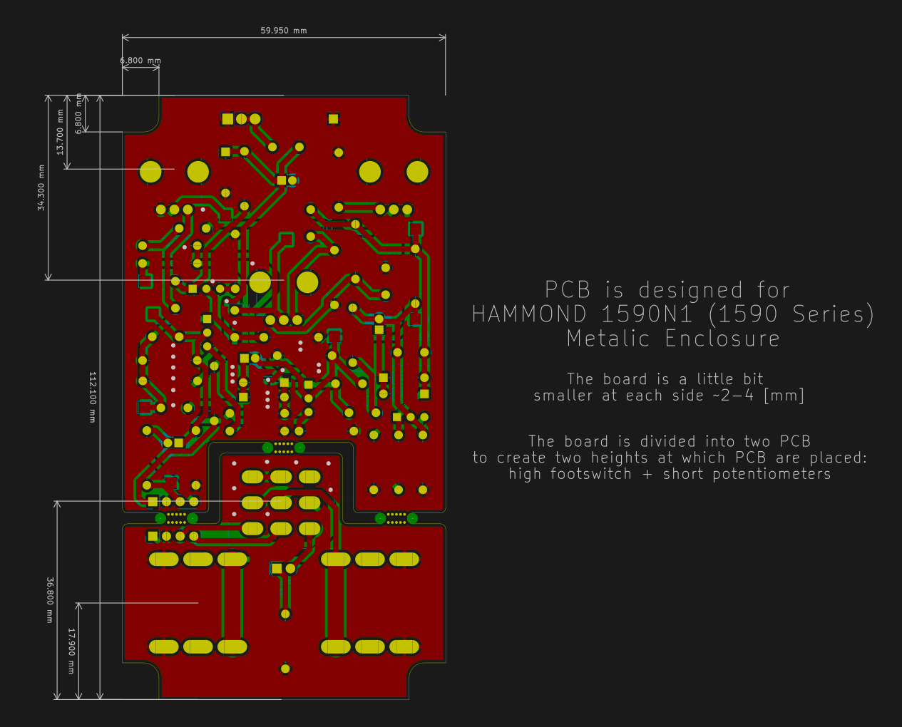
Fuzzpedal is an open-source printed circuit board by alberand, from the alberand/fuzzpedal repository on GitHub. It is a 2-layer board of 60 × 112.1 mm with 71 parts on 35 nets, routed with 250 tracks and 32 vias.
Its parts include 23 resistors, 14 capacitors, 6 diodes, 4 transistors and 3 connectors. It belongs with the audio and music boards of this library.
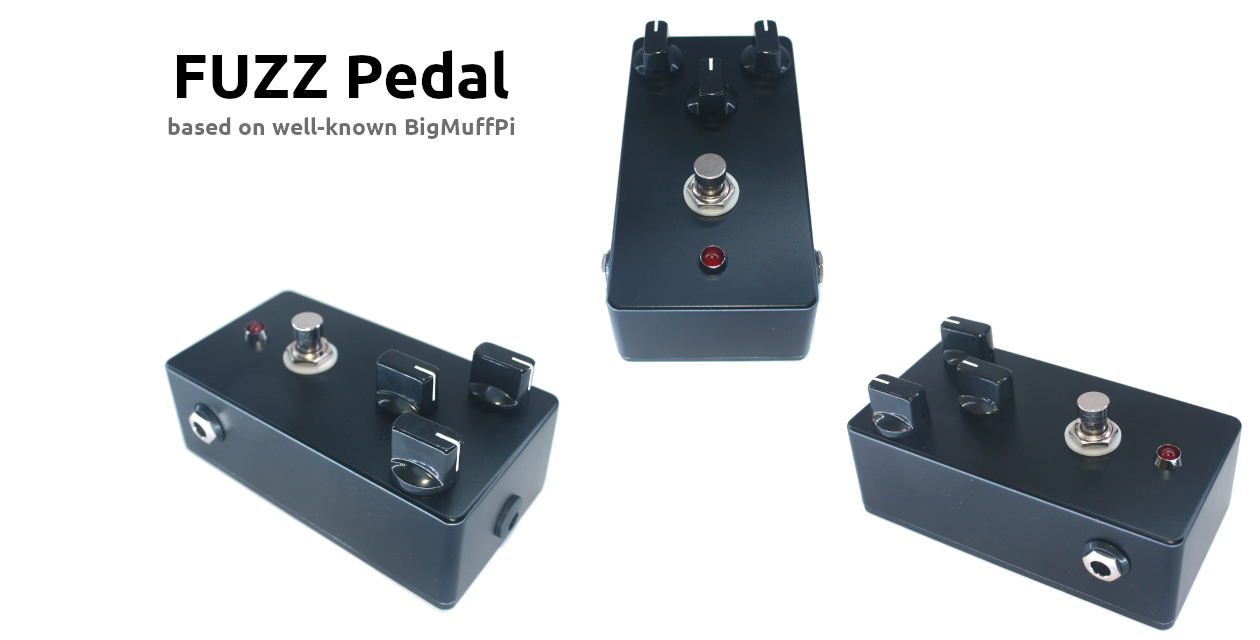
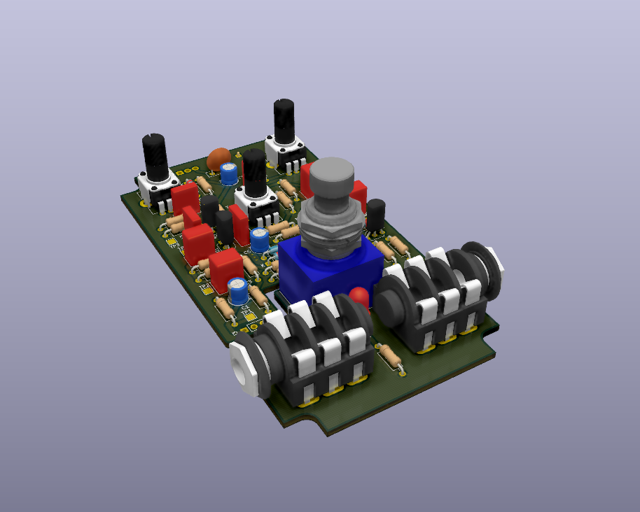
This repository contains a lot of information on how to build a Fuzz Pedal based on well-known Big Muff PI pedal.



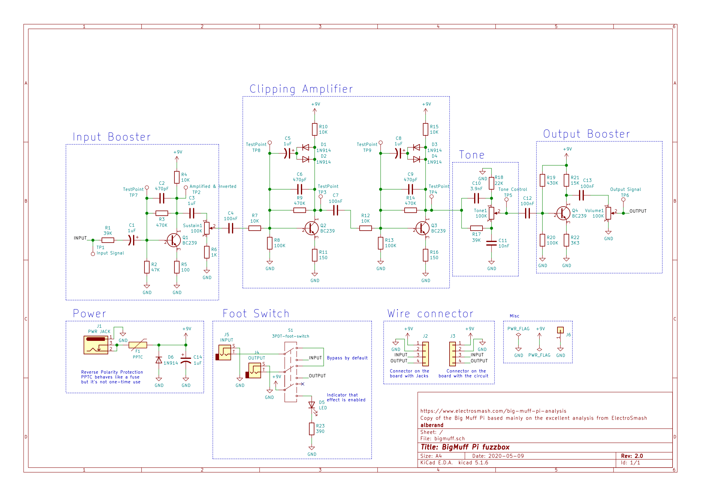
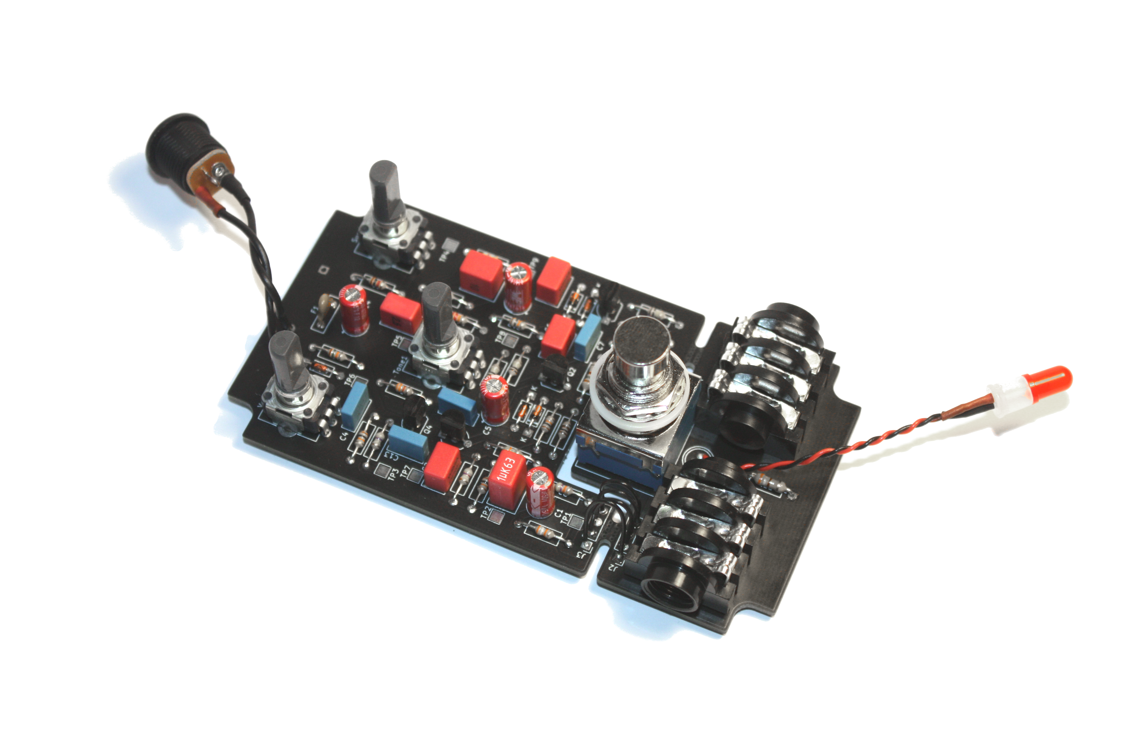
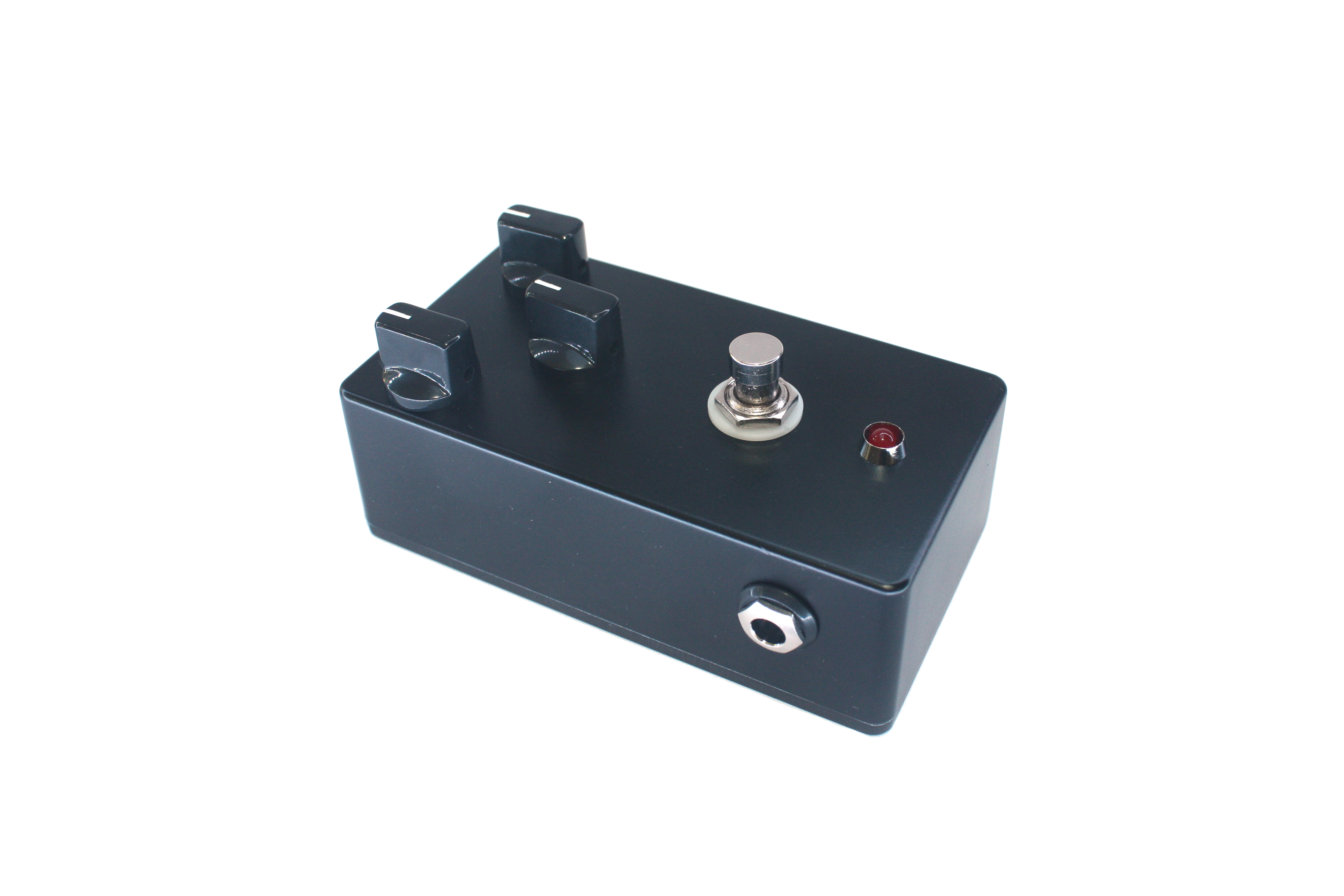
Here is crude cost calculation of one Pedal. Remember that this doesn't include any tools. The shipping price could vary (in my case I had many more parcels 😕). In total one pedal cost about 50 - 60 💶 euro (without shipping) + you would have a few paint sprays.
| Material Type | Quantity | Price [EUR] |
|---|---|---|
| PCB | 5 (min amount) | 8.5 |
| Electronic components & Misc | 1 set | 25 |
| Case | 1 | 11 |
| Ground & Color & Clear Paint | 3 | 6x3 |
| Shipping | ~4 | 20x4 |
How long does it take to make a pedal? If you have any experience in soldering, painting it will take somewhere around 33 hours mainly due waiting for paint to dry.
| Activity Type | Time [hours] |
|---|---|
| Board Soldering | 5 |
| Case drilling | 2 |
| Case cleaning & polishing | 0.5 |
| Case painting | 25 |
| Assembling | 0.5 |
TODO In progress
The assebmly process is quite simple. The most time-consuming part is PCB soldering. Otherwise, you just need to put PCB into box.
TODO describe what instruments to use
| Qty | Value | Footprint | References |
|---|---|---|---|
| 5 | 10K | Resistor_THT:R_Axial_DIN0207_L6.3mm_D2.5mm_P10.16mm_Horizontal | R4, R7, R10, R12, R15 |
| 5 | 1N914 | Diode_THT:D_DO-35_SOD27_P7.62mm_Horizontal | D1, D2, D3, D4, D6 |
| 5 | TestPoint | TestPoint:TestPoint_Pad_2.0x2.0mm | TP3, TP4, TP7, TP8, TP9 |
| 4 | 100nF | Capacitor_THT:C_Rect_L7.2mm_W2.5mm_P5.00mm_FKS2_FKP2_MKS2_MKP2 | C4, C7, C12, C13 |
| 4 | 1uF | Capacitor_THT:CP_Radial_D5.0mm_P2.00mm | C1, C5, C8, C14 |
| 4 | BC239 | Package_TO_SOT_THT:TO-92L_Inline_Wide | Q1, Q2, Q3, Q4 |
| 3 | 100K | Resistor_THT:R_Axial_DIN0207_L6.3mm_D2.5mm_P10.16mm_Horizontal | R8, R13, R20 |
| 3 | 100K | Potentiometer_THT:Potentiometer_Alps_RK09K_Single_Vertical | Sustain1, Tone1, Volume1 |
| 3 | 470K | Resistor_THT:R_Axial_DIN0207_L6.3mm_D2.5mm_P10.16mm_Horizontal | R3, R9, R14 |
| 3 | 470pF | Capacitor_THT:C_Rect_L7.2mm_W4.5mm_P5.00mm_FKS2_FKP2_MKS2_MKP2 | C2, C6, C9 |
| 3 | VAL** | MouseBite:mouse-bite-2mm-slot | mouse-bite-2mm-slot, mouse-bite-2mm-slot, mouse-bite-2mm-slot |
| 2 | 150 | Resistor_THT:R_Axial_DIN0207_L6.3mm_D2.5mm_P10.16mm_Horizontal | R11, R16 |
| 2 | 39K | Resistor_THT:R_Axial_DIN0207_L6.3mm_D2.5mm_P10.16mm_Horizontal | R1, R17 |
| 1 | 100 | Resistor_THT:R_Axial_DIN0207_L6.3mm_D2.5mm_P10.16mm_Horizontal | R5 |
| 1 | 10nF | Capacitor_THT:C_Rect_L7.2mm_W5.5mm_P5.00mm_FKS2_FKP2_MKS2_MKP2 | C11 |
| 1 | 15K | Resistor_THT:R_Axial_DIN0207_L6.3mm_D2.5mm_P10.16mm_Horizontal | R21 |
| 1 | 1K | Resistor_THT:R_Axial_DIN0207_L6.3mm_D2.5mm_P10.16mm_Horizontal | R6 |
| 1 | 1uF | Capacitor_THT:C_Rect_L7.2mm_W5.5mm_P5.00mm_FKS2_FKP2_MKS2_MKP2 | C3 |
| 1 | 22K | Resistor_THT:R_Axial_DIN0207_L6.3mm_D2.5mm_P10.16mm_Horizontal | R18 |
| 1 | 3.9nF | Capacitor_THT:C_Rect_L7.2mm_W4.5mm_P5.00mm_FKS2_FKP2_MKS2_MKP2 | C10 |
| 1 | 390 | Resistor_THT:R_Axial_DIN0207_L6.3mm_D2.5mm_P10.16mm_Horizontal | R23 |
| 1 | 3K3 | Resistor_THT:R_Axial_DIN0207_L6.3mm_D2.5mm_P10.16mm_Horizontal | R22 |
| 1 | 3PDT-foot-switch | bigmuffpi:SF17020F-0302-21R-L | S1 |
| 1 | 430K | Resistor_THT:R_Axial_DIN0207_L6.3mm_D2.5mm_P10.16mm_Horizontal | R19 |
| 1 | 47K | Resistor_THT:R_Axial_DIN0207_L6.3mm_D2.5mm_P10.16mm_Horizontal | R2 |
| 1 | Amplified & Inverted | TestPoint:TestPoint_Pad_2.0x2.0mm | TP2 |
| 1 | GND for scope | Connector_PinHeader_2.54mm:PinHeader_1x01_P2.54mm_Vertical | Je |
| 1 | INPUT | bigmuffpi:NMJ6HC-S | INPUT |
| 1 | Input Signal | TestPoint:TestPoint_Pad_2.0x2.0mm | TP1 |
| 1 | LED | LED_THT:LED_D5.0mm | D5 |
| 1 | OUTPUT | bigmuffpi:NMJ6HC-S | OUTPUT |
| 1 | Output Signal | TestPoint:TestPoint_Pad_2.0x2.0mm | TP6 |
| 1 | PPTC | Capacitor_THT:C_Disc_D8.0mm_W2.5mm_P5.00mm | F1 |
| 1 | PWR JACK | Connector_PinHeader_2.54mm:PinHeader_1x03_P2.54mm_Vertical | J1 |
| 1 | Tone Control | TestPoint:TestPoint_Pad_2.0x2.0mm | TP5 |
| 1 | Wire connector (circuit) | Connector_PinHeader_2.54mm:PinHeader_1x04_P2.54mm_Vertical | J3 |
| 1 | Wire connector (smol) | Connector_PinHeader_2.54mm:PinHeader_1x04_P2.54mm_Vertical | J2 |
The 70 most common of 71 parts.
hackclub/OnBoard
💡 Join 1,000 teenagers and make your first PCB with a $100 grant!


hydrabus/hydrabus
HydraBus open source multi-tool for anyone interested in learning/developping/debugging/hacking/Penetration Testing for basic or advanced embedded hardware

beekeeb/Allium58
The Allium58 is created based on the Lily58 Pro, designed to enhance wireless capabilities and provide compatibility with GLP (Gateron Low Profile) hotswap sockets.


siderakb/ergo-snm-keyboard
ErgoSNM is a split ergonomic keyboard integrated with trackball, wireless is in beta

cnlohr/cnhardware
My dumping grounds for all my kicad projects and random hardware bringup.
It measures 60 × 112.1 mm and has 2 copper layers, 1.6 mm thick.
71 parts. The full list of its parts is on this page, with links to each part's symbol and footprint where PCBKit's library has them.
From the alberand/fuzzpedal repository on GitHub, at the commit this page was made from: the board is fuzzpedal/fuzzpedal.kicad_pcb. PCBKit opens the board in the browser, with nothing to install.
Its repository states no licence, so its author keeps all rights: ask alberand before reusing the design.