2 layers96.8 × 49.8 mm
R1.4 MaxDuino KiCad Files
Alan-Lomax/MaxDuino
All in One PCB Arduino Carrier for Model Railways
57 parts2GPL-3.0
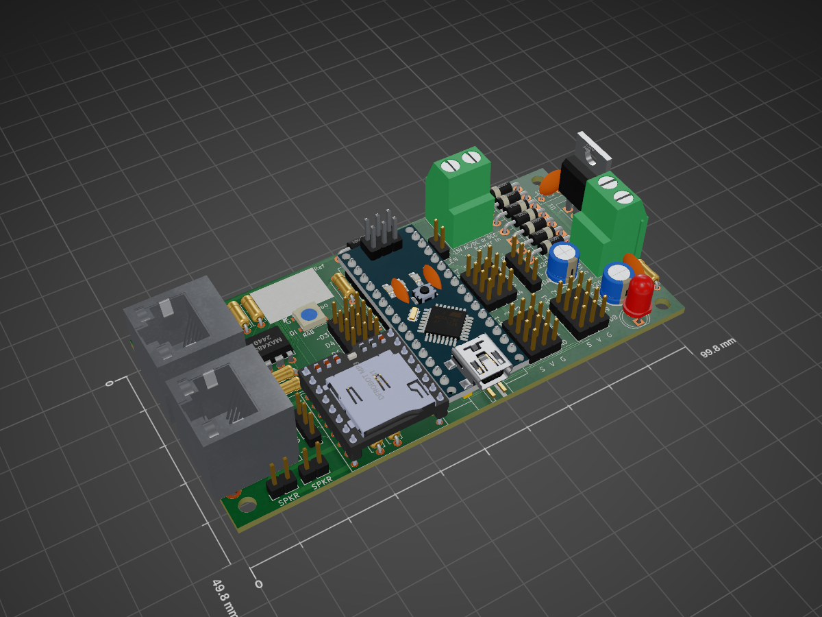
 Alan-Lomax/MaxDuino2
All in One PCB Arduino Carrier for Model Railways
MaxDuino R1.6 is an open-source printed circuit board by Alan-Lomax, from the Alan-Lomax/MaxDuino repository on GitHub, published under the GPL-3.0 licence. It is a 2-layer board of 99.8 × 49.8 mm with 66 parts on 61 nets, routed with 383 tracks and 10 vias.
It is built around the MAX485ED and L7805. Its parts include 22 connectors, 14 resistors, 11 diodes, 7 capacitors and 4 ICs. It belongs with the AVR (ATmega, ATtiny) boards of this library.


Is a small PCB carrier board that acts as a host for an Arduino NANO. The PCB provides a multitude of supporting features for the NANO. It is targeted for use as a model railway animation tool (see feature list) Because of its flexibility it can be used in many different scenarios.
There are two current versions according to needs:
Since the R1.4 version
The KiCad files are essentially 'source code' and include:
The Gerber files can be thought of as the 'compiled version'. The Gerbers are seperate files, one for each step in the manufacturing process of a PCB. The Gerbers are normally saved as a ZIP file and the Zip file is what gets submitted for manufacture at the fabrication facility of your choice.
The MaxDuino PCB is sized 50 mm x 100 mm which means it can easily be panelized in sets of two. This makes the panelized Maxduino fit on a single 100 mm x 100 mm PCB which is the normal 'minimum size' for billing. The short version of this is you get twice as many MaxDuinos at no extra cost.
There is a seperate folder containing the Panelized version of the Gerbers.
Normally all EDITS should be done to the 'single PCB' and then it be repanelized To repanelize you start a new Kicad project (one with no contents) and run a 'plug in' to panelize things. You will specfiy which other file has the PCB layout you want to panelize. You also set the number of rows (2) and collumns (1) The only manual step needed is to add a horizontal line on the edge cut layer. This will be a 'Vee-Cut' and allows separating the two PCBs easily.
| Qty | Value | Footprint | References |
|---|---|---|---|
| 8 | 1N4001 | Diode_THT:D_DO-41_SOD81_P10.16mm_Horizontal | D1, D2, D3, D4, D5, D6, D7, D11 |
| 4 | +5 | Connector_PinHeader_2.54mm:PinHeader_1x04_P2.54mm_Vertical | J4-2, J5-2, J6-2, J7-2 |
| 4 | 100nF | Capacitor_THT:C_Disc_D7.0mm_W2.5mm_P5.00mm | C2, C3, C6, C8 |
| 4 | 10K | Resistor_THT:R_Axial_DIN0207_L6.3mm_D2.5mm_P7.62mm_Horizontal | R3, R10, R11, R12 |
| 4 | GND | Connector_PinHeader_2.54mm:PinHeader_1x04_P2.54mm_Vertical | J4-3, J5-3, J6-3, J7-3 |
| 4 | I/O | Connector_PinHeader_2.54mm:PinHeader_1x04_P2.54mm_Vertical | J4-1, J5-1, J6-1, J7-1 |
| 4 | M3 | MountingHole:MountingHole_3.2mm_M3 | M3.1, M3.2, M3.3, M3.4 |
| 2 | 20K | Resistor_THT:R_Axial_DIN0207_L6.3mm_D2.5mm_P7.62mm_Horizontal | R8, R9 |
| 2 | 220uF | Capacitor_THT:CP_Radial_D6.3mm_P2.50mm | C1, C4 |
| 2 | RS-485 | Connector_RJ:RJ45_Ninigi_GE | J9, J10 |
| 2 | SPKR | Connector_PinHeader_2.54mm:PinHeader_1x02_P2.54mm_Vertical | J4, J5 |
| 1 | .001uF | Capacitor_THT:C_Disc_D7.0mm_W2.5mm_P5.00mm | C5 |
| 1 | 0R | Resistor_SMD:R_0805_2012Metric | R14 |
| 1 | 120R | Resistor_THT:R_Axial_DIN0207_L6.3mm_D2.5mm_P7.62mm_Horizontal | R7 |
| 1 | 15V AC/DC or DCC | TerminalBlock_Phoenix:TerminalBlock_Phoenix_MKDS-3-2-5.08_1x02_P5.08mm_Horizontal | J1 |
| 1 | 1K | Resistor_THT:R_Axial_DIN0207_L6.3mm_D2.5mm_P7.62mm_Horizontal | R6 |
| 1 | 1N914 | Diode_THT:D_DO-35_SOD27_P7.62mm_Horizontal | D9 |
| 1 | 2K2 | Resistor_THT:R_Axial_DIN0207_L6.3mm_D2.5mm_P7.62mm_Horizontal | R2 |
| 1 | 330R | Resistor_THT:R_Axial_DIN0207_L6.3mm_D2.5mm_P7.62mm_Horizontal | R13 |
| 1 | 470R | Resistor_THT:R_Axial_DIN0207_L6.3mm_D2.5mm_P7.62mm_Horizontal | R4 |
| 1 | 5V DC | TerminalBlock_Phoenix:TerminalBlock_Phoenix_MKDS-3-2-5.08_1x02_P5.08mm_Horizontal | J7 |
| 1 | 6.8K | Resistor_THT:R_Axial_DIN0207_L6.3mm_D2.5mm_P7.62mm_Horizontal | R1 |
| 1 | 680R | Resistor_THT:R_Axial_DIN0207_L6.3mm_D2.5mm_P7.62mm_Horizontal | R5 |
| 1 | 6N137 | Package_DIP:DIP-8_W7.62mm | U2 |
| 1 | Arduino_Nano_v3.x | Module:Arduino_Nano | A1 |
| 1 | Audio | Connector_PinHeader_2.54mm:PinHeader_1x03_P2.54mm_Vertical | J6 |
| 1 | DCC Signal | Connector_PinHeader_2.54mm:PinHeader_1x02_P2.54mm_Horizontal | J2 |
| 1 | DFRobot MP3 | Module_DFR0299.Library:MODULE_DFR0299 | U4 |
| 1 | EOL | Connector_PinHeader_2.54mm:PinHeader_1x02_P2.54mm_Vertical | JR1 |
| 1 | I2C | Connector_PinHeader_2.54mm:PinHeader_1x04_P2.54mm_Vertical | J8 |
| 1 | Inolux_IN-PI554FCH | LED_SMD:LED_Inolux_IN-PI554FCH_PLCC4_5.0x5.0mm_P3.2mm | D10 |
| 1 | L7805 | Package_TO_SOT_THT:TO-220-3_Vertical | U1 |
| 1 | LOGO | MERG_LOGO:MERG_LOGO | MERG |
| 1 | MAX485E | Package_DIP:DIP-8_W7.62mm | U3 |
| 1 | PWR | LED_THT:LED_D5.0mm | D8 |
| 1 | Vin_EN | Connector_PinHeader_2.54mm:PinHeader_1x02_P2.54mm_Vertical | J3 |
The 65 most common of 66 parts.
It measures 99.8 × 49.8 mm and has 2 copper layers, 1.6 mm thick.
66 parts, built around the MAX485ED and L7805. The full list of its parts is on this page, with links to each part's symbol and footprint where PCBKit's library has them.
From the Alan-Lomax/MaxDuino repository on GitHub, at the commit this page was made from: the board is R1.6 (With RJ45)/R1.6 MaxDuino KiCad Files/MaxDuino_R1.6.kicad_pcb and its schematic R1.4 (With screw Terminals)/R1.4 MaxDuino KiCad Files/R1.4 MaxDuino KiCad Files.kicad_sch. PCBKit opens the board in the browser, with nothing to install.
Its repository publishes it under the GPL-3.0 licence: you may reuse it on that licence's terms (keep the author's notice, and for a copyleft licence share your changes alike).
Alan-Lomax/MaxDuino
All in One PCB Arduino Carrier for Model Railways

ernest-czachorowski/Flood-Sensors-KiCad-Files
This repository contains KiCad files for my master's thesis IoT infrastructure, which includes water leak detection sensors.


