KRC-3006 Pass-Through Breakout Board (DN-KRC3006-04)
Purpose
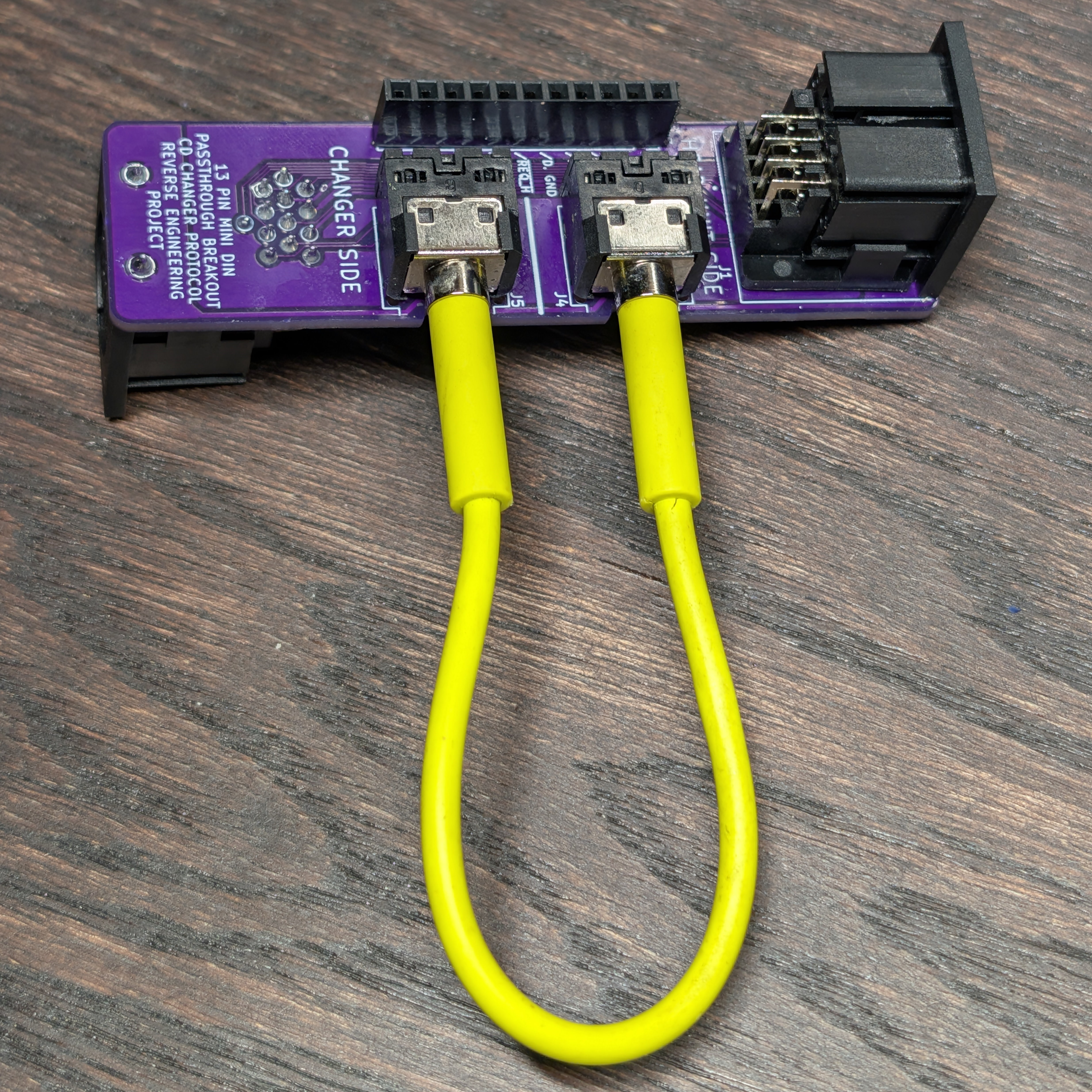
This KiCad project implements a passive, pass-through breakout board for the Kenwood KRC-3006 head unit's 13-pin mini DIN connector. The board provides:
- Signal routing between the KRC-3006 and connected CD autochanger.
- Accessible test points for bus signal analysis and protocol reverse engineering.
- Isolated audio path with independent head unit and changer TRS audio jack connectors.
Current Status
COMPLETE AND TESTED — Boards received 2026-03-28 from OSH Park. S/N 1 verification completed 2026-04-10, per TL-02-01-20260410. Its step 1.1 result remains a closeout question (DC-13). Breakout board is fully functional and ready for protocol reverse engineering work.
Schematic Summary
| Ref Des | Component | Function |
|---|
| J1 | SDD-130J, 13-pin mini DIN female | Head unit side connector (front side) |
| J2 | SDD-130J, 13-pin mini DIN female | Changer side connector (back side) |
| J3 | 1×11 female pin header, 2.54 mm pitch | Digital/control signal test points |
| J4 | STX-3100-3NB, 3.5 mm TRS audio jack | Head unit side audio breakout |
| J5 | STX-3100-3NB, 3.5 mm TRS audio jack | Changer side audio breakout |
J1/J2 Pinout
| Pin | Signal | Description |
|---|
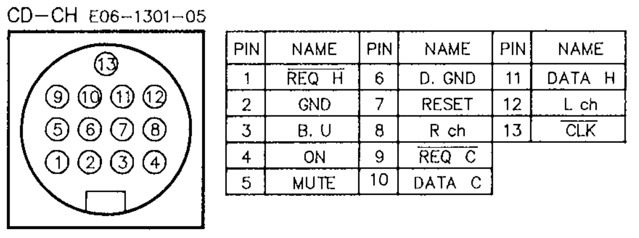
| 1 | REQ H (Active Low) | Request handshake output from head unit. |
| 2 | GND | Ground (factory name; DN-02 §1). |
| 3 | B.U. | Battery Unswitched. |
| 4 | ON | Changer connect/enable signal. |
| 5 | MUTE | Mute request line. |
| 6 | D. GND | Digital ground. |
| 7 | RESET | Reset pulse output to changer. |
| 8 | R CH | Right audio channel, analog. |
| 9 | REQ C (Active Low) | Request handshake output from changer to head unit. |
| 10 | DATA C | Serial data from changer to head unit. |
| 11 | DATA H | Serial data from head unit to changer. |
| 12 | L CH | Left audio channel, analog. |
| 13 | CLK (Active Low) | Synchronous clock. |
J3 Pinout
| J3 Pin | J1 Pin | Signal |
|---|
| 1 | 2 | GND |
| 2 | 4 | ON (CH-CON) |
| 3 | 3 | B.U. (+14V) |
| 4 | 7 | RESET |
| 5 | 6 | D. GND |
| 6 | 1 | REQ H (Active Low) |
| 7 | 9 | REQ C (Active Low) |
| 8 | 5 | MUTE |
| 9 | 10 | DATA C |
| 10 | 11 | DATA H |
| 11 | 13 | CLK (Active Low) |
J4 Pinout
| J4 contact | J1 pin | Signal |
|---|
| Tip | 8 | R ch (to head unit) |
| Ring | 12 | L ch (to head unit) |
| Sleeve | 2 | GND |
J5 Pinout
| J5 contact | J2 pin | Signal |
|---|
| Tip | 8 | R ch (from changer) |
| Ring | 12 | L ch (from changer) |
| Sleeve | 2 | GND |
These are contact labels, not numbered pins. Mapping follows approved R-4, which cites the PCB and TL-02 steps 1.12–1.13 and 3.3–3.4. This corrects the README labels only.
Audio Interception
The audio channels (Pin 8 - R CH and Pin 12 L CH) are not routed as a direct pass-through between J1 and J2. Instead, they are broken out to two 3.5 mm TRS audio jacks mounted on the right edge of the board:
- J4 — Head unit side audio. Tip = R CH, Ring = L CH, Sleeve = GND.
- J5 — Changer side audio. Tip = R CH, Ring = L CH, Sleeve = GND.
The audio jacks use a standard 3-conductor (TRS) footprint with no switching contacts. When nothing is plugged in, the audio pins on both the head unit and changer sides float.
This topology enables three operating modes:
| Mode | Configuration | Use Case |
|---|
| Audio pass-through | Connect J4 to J5 with a male-to-male 3.5 mm TRS cable. | Normal protocol capture with authentic changer audio reaching the head unit. |
| Audio intercept | Connect monitoring equipment (oscilloscope, audio recorder, powered speakers) to J5. | Listen to or record the changer's audio output without routing it to the head unit. |
| Audio injection | Connect an external audio source to J4. Leave J5 disconnected or connected to monitoring equipment. | Feed test tones or music from a phone, DAC, or Raspberry Pi directly into the head unit's audio input path. Useful for verifying the audio path independently of changer protocol state. |
Audio pass-through requires the external cable. The board cannot function as a fully transparent sniffer without it. This is an intentional design decision — the separate jacks provide flexibility that a hardwired pass-through cannot.
Next Steps
S/N 1 supported TP-01 Phase 1 on 2026-04-19. Next, follow TP-01 Rev C:
- Phase 2A: inline capture with the C717 connected and no magazine, after Phase 1 closeout.
- Phase 2B: loaded-changer initialization, steady playback, power-on and time-field captures.
- Phase 2C: CLK driver identification with FIX-01, modified S/N 2, built and verified per DN-04 §16. Keep S/N 1 unmodified.
- Phase 3: command mapping, followed by TP-03 emulator development and integration.
For every analyzer connection follow DN-04 §7: power down, block J3-3, ground only at J3-1, leave J3-5 empty, use the custom crimped harness and cover exposed rear joints (R-2).
References
- Service manual: Kenwood KRC-3006 Cassette Head Unit
- Service manual: Kenwood KDC-C717 CD Changer
- Related design docs: DN-KRC3006-02 (Schematic Analysis), DN-KRC3006-04
Revision History
| Rev | Date | Author | Changes |
|---|
| — | 2026-10-17 | A. Kreager | R-4: correct J4/J5 contact and channel labels. DC-05/13: factory ground name, recorded completion date and TP-01 Rev C work order; link FIX-01 instructions. |


