4 layers121.2 × 72 mm
Facs pcb v2
czbiohub-sf/2023-facs-automation-pub
Python libraries for automating cell sorting with the Sony SH800S GUI.
139 parts1BSD-3-Clause

 akashihi/P11
ESPHome interface for Panasonic air conditioners and heat pumps (CN-CNT)
P11 is an open-source printed circuit board by akashihi, from the akashihi/P11 repository on GitHub, published under the GPL-3.0 licence. It is a 4-layer board of 48 × 30 mm with 12 parts on 19 nets, routed with 50 tracks and 7 vias.
It is built around the DS18B20, AO3400A and US1A. Its parts include 5 resistors, 2 ICs, 2 transistors, 1 capacitor and 1 diode. It belongs with the home automation and IoT and interfaces and adapters boards and the ESP32 and RISC-V boards of this library.


A small open-hardware board that connects a Panasonic air conditioner or air-to-air heat pump to
Home Assistant through the indoor unit's CN-CNT service port.
It runs ESPHome on an ESP32-C3 Super Mini with the
panasonic_ac component. Everything stays
local: no Panasonic cloud and no Comfort Cloud adapter (CZ-TACG1).
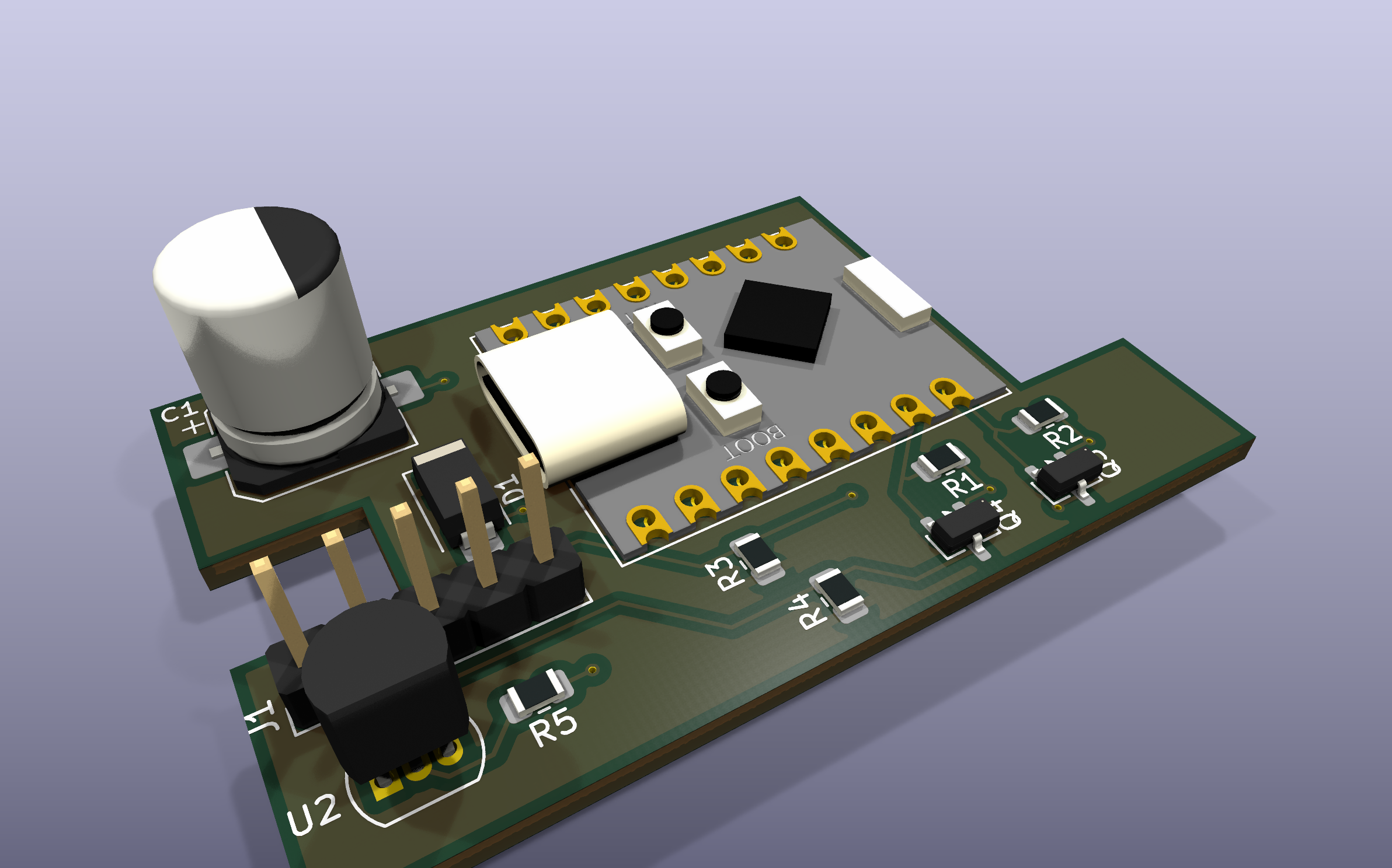
This design is based on the Ingenious Makers ESPHome Panasonic Climate Interface. Compared with the original, it:
| MCU | ESP32-C3 Super Mini (4 MB flash) |
| Interface | UART, 9600 baud, 8E1, 5 V logic on the AC side |
| Level shifting | 2× AO3400A, bidirectional MOSFET shifter (3.3 V ↔ 5 V) |
| Power | 5 V from CN-CNT pin 1, 470 µF bulk capacitor, US1A reverse-polarity diode |
| PCB | 48 × 30 mm, 4 layers, 1.6 mm (F.Cu signals / In1 GND / In2 +3V3 / B.Cu) |
| EDA | KiCad 10 |
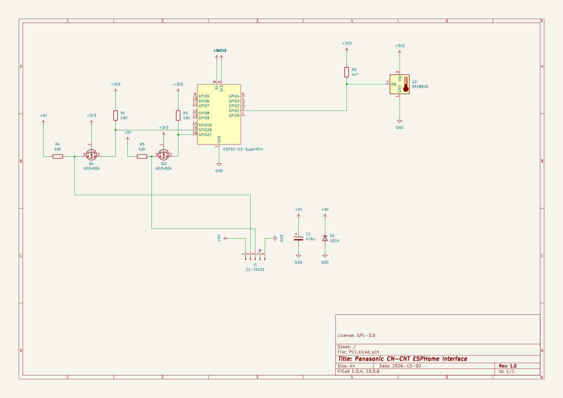
You can also get the schematic as a PDF: docs/schematic.pdf.
Level shifter. Each signal uses the classic single-MOSFET bidirectional shifter. The AO3400A gate is tied to +3V3. The source goes to the ESP32 pin with a 10 kΩ pull-up to 3.3 V, and the drain goes to the CN-CNT pin with a 10 kΩ pull-up to 5 V.
Power. The ESP32-C3 Super Mini is powered through its 5V pin from CN-CNT pin 1, and its
on-board regulator supplies the 3.3 V rail. D1 sits reverse-biased across the 5 V input and
conducts if the cable is plugged in the wrong way round.
J1 – CN-CNT (pin 1 is the end nearest the board edge, next to U2)
| J1 pin | CN-CNT signal | Connected to |
|---|---|---|
| 1 | +5 V | ESP32 5V, C1, D1 |
| 2 | TX (AC → board) | Q4 → GPIO20 (ESP RX) |
| 3 | RX (board → AC) | Q3 → GPIO21 (ESP TX) |
| 4 | +12 V | not connected; the board ignores the 12 V line |
| 5 | GND | GND |
[!WARNING] CN-CNT pin 4 carries 12 V. The board leaves it unconnected, but a cable with the wrong pin order can still put 12 V on the 5 V or signal lines, and that destroys the board and can damage the indoor unit's controller. Check your cable with a multimeter before plugging it in, and always switch the unit off at the breaker before you open the indoor unit.
The CN-CNT socket on the indoor unit is a JST PA series header, 5 pins at 2.0 mm pitch, which mates with a JST PAP-05V-S housing. J1 on the board is a standard 2.54 mm pin header, so the two need an adapter cable:
Wire it straight through, pin 1 → pin 1 through pin 5 → pin 5. You can leave the pin 4 (12 V) wire out, because J1 pin 4 isn't connected anyway.
| Ref | Qty | Value | Description | Package |
|---|---|---|---|---|
| U1 | 1 | ESP32-C3 Super Mini | ESP32-C3 dev board with USB-C | Module, 2× 8 pin |
| Q3, Q4 | 2 | AO3400A | N-channel MOSFET, 30 V / 5.7 A, logic level | SOT-23 |
| D1 | 1 | US1A | 50 V / 1 A fast rectifier, reverse-polarity protection | SMA (DO-214AC) |
| C1 | 1 | 470 µF | Electrolytic capacitor, ≥ 10 V | SMD 8 × 10.5 mm |
| R1–R4 | 4 | 10 kΩ | Level shifter pull-ups | 0805 |
| R5 | 1 | 4.7 kΩ | 1-Wire pull-up | 0805 |
| U2 | 1 | DS18B20 | 1-Wire temperature sensor (optional) | TO-92 |
| J1 | 1 | 1×5 header | 2.54 mm pin header | THT |
You also need the adapter cable from the CN-CNT socket to J1 (see Cable): 1× JST PAP-05V-S housing, 5× SPHD-001T-P0.5 crimp contacts, 1× 5-pin 2.54 mm Dupont housing with contacts, and some wire.
Any logic-level N-MOSFET in SOT-23 with VGS(th) well below 3.3 V can replace the AO3400A, for example BSS138 or 2N7002.
P11/P11.kicad_pcb in KiCad
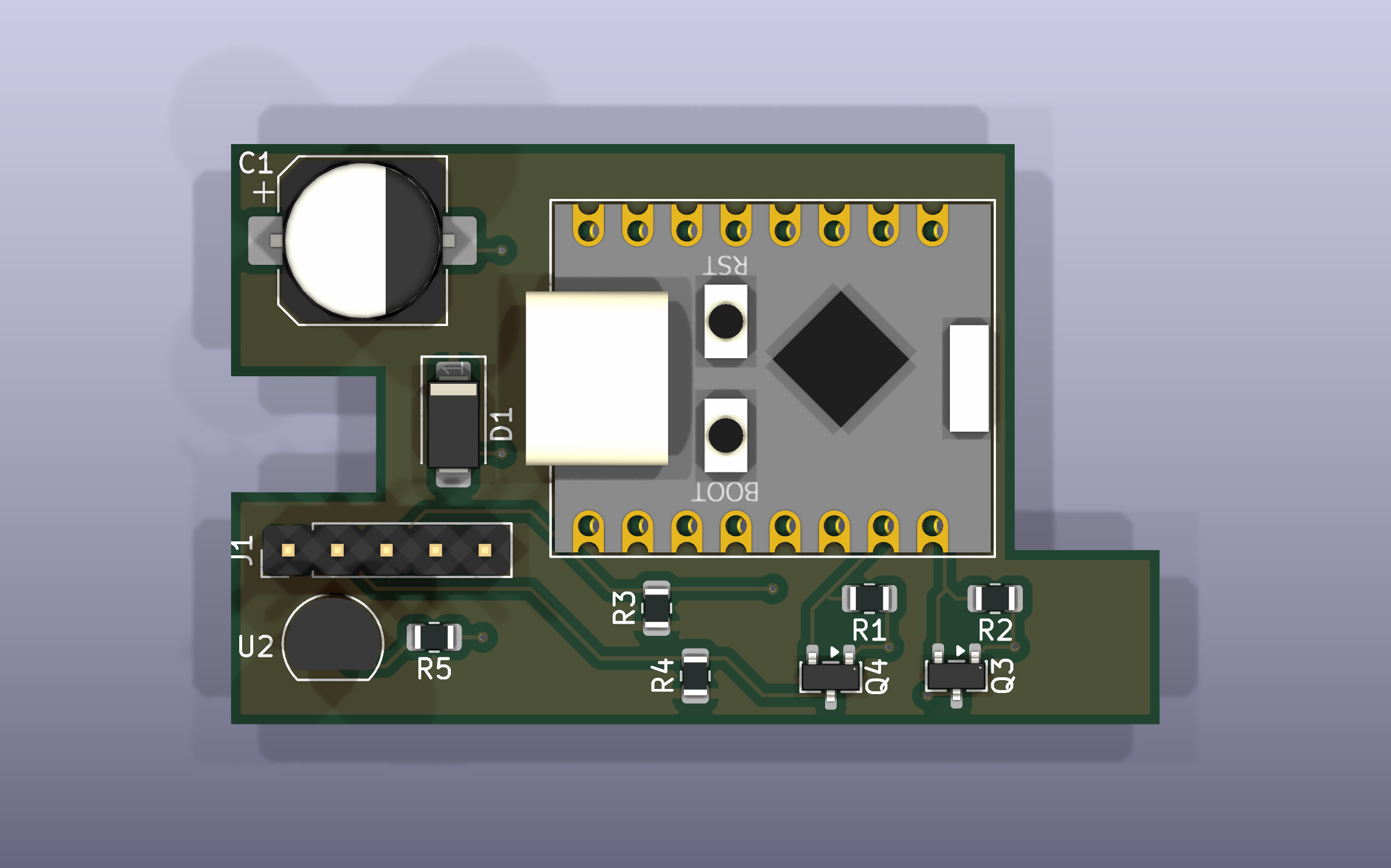
(File → Fabrication Outputs), and order it as a 4-layer board.Use this top view as a placement reference. J1 pin 1 is on the left, at the board edge.
[!CAUTION] Don't power the board from USB and the CN-CNT port at the same time. Many ESP32-C3 Super Mini clones have no diode between USB VBUS and the
5Vpin, so the two supplies would back-feed each other.
The ESPHome configuration is in panasonic-cn-cnt.yml. It uses the
panasonic_ac external component in cnt mode:
uart:
  tx_pin: GPIO21
  rx_pin: GPIO20
  baud_rate: 9600
  parity: EVEN

climate:
  - platform: panasonic_ac
    type: cnt
    # ...
Before you flash it:
secrets.yaml.example to secrets.yaml, in the same folder as the YAML file.openssl rand -base64 32 and put it in
api_encryption_key.secrets.yaml is listed in .gitignore, so it won't be committed by accident.
Then flash it:
esphome run panasonic-cn-cnt.ymlThe first flash has to go over USB. Do it before you solder the module in, or use an angled USB-C cable on an assembled board (see Known issues). If the board isn't detected, hold BOOT while you plug in USB. After that you can update the firmware over Wi-Fi. Home Assistant finds the device on its own through the ESPHome integration.
rev 1.0: a straight USB-C cable doesn't fit. On the assembled board, capacitor C1 sits right in front of the ESP32-C3 Super Mini's USB-C socket and blocks a straight USB-C plug. For the first flash you need either:
After the first flash, updates go over Wi-Fi, so this only affects the first flash and recovering a board that won't boot. If there is a rev 2, it will fix this by moving C1 out of the way of the connector.
This project is licensed under the GNU General Public License v3.0. The license covers the hardware design files, documentation and ESPHome configuration.
This project is not affiliated with or endorsed by Panasonic. Opening your indoor unit and connecting third-party hardware may void its warranty. You build and use this project at your own risk.
| Qty | Value | Footprint | References |
|---|---|---|---|
| 4 | 10K | Resistor_SMD:R_0805_2012Metric | R1, R2, R3, R4 |
| 2 | AO3400A | Package_TO_SOT_SMD:SOT-23 | Q3, Q4 |
| 1 | 470u | Capacitor_SMD:CP_Elec_8x10.5 | C1 |
| 1 | 4k7 | Resistor_SMD:R_0805_2012Metric | R5 |
| 1 | CZ-TACG1 | Connector_PinHeader_2.54mm:PinHeader_1x05_P2.54mm_Vertical | J1 |
| 1 | DS18B20 | Package_TO_SOT_THT:TO-92_Inline | U2 |
| 1 | ESP32-C3-SuperMini | ESP32-C3-SuperMini:ESP32-C3-SuperMini | U1 |
| 1 | US1A | Diode_SMD:D_SMA | D1 |
It measures 48 × 30 mm and has 4 copper layers, 1.6 mm thick.
12 parts, built around the DS18B20, AO3400A and US1A. The full list of its parts is on this page, with links to each part's symbol and footprint where PCBKit's library has them.
From the akashihi/P11 repository on GitHub, at the commit this page was made from: the board is P11/P11.kicad_pcb and its schematic P11/P11.kicad_sch. PCBKit opens the board in the browser, with nothing to install.
Its repository publishes it under the GPL-3.0 licence: you may reuse it on that licence's terms (keep the author's notice, and for a copyleft licence share your changes alike).
czbiohub-sf/2023-facs-automation-pub
Python libraries for automating cell sorting with the Sony SH800S GUI.

tomcircuit/Apple2PicoPSU
12V Input Power Supply retrofit for vintage Apple //e computers

aditya-1225/weather-station-PCB
If the data is sent to the nRF24L01+PA+LNA module, another PCB acts as the receiver and transmits the received data to a computer through the serial port.

chr1snv/CRT-Driver
Design for an Electron Microscope also Minimal Analog Circuit Board to drive a CRT from vga signals from a bnc cable


libertathiest/fs10-atmega32u4-monitor
A standalone USB monitor and configuration tool for the FCI FS10 Flow Switch, built around the ATmega32U4 on an Arduino Leonardo–compatible board.


waterloo-rocketry/daq
Data Acquisition schematics, boards, datasheets, docs, and software