
2 layers99.7 × 48.3 mm
Texteditor
ajackson2681/codex
The Codex is an attempt at an open-source, distraction-free writing device inspired somewhat by the AlphaSmart Neo (at least the display was).
18 parts1GPL-3.0
 ajackson2681/codex1
The Codex is an attempt at an open-source, distraction-free writing device inspired somewhat by the AlphaSmart Neo (at least the display was).
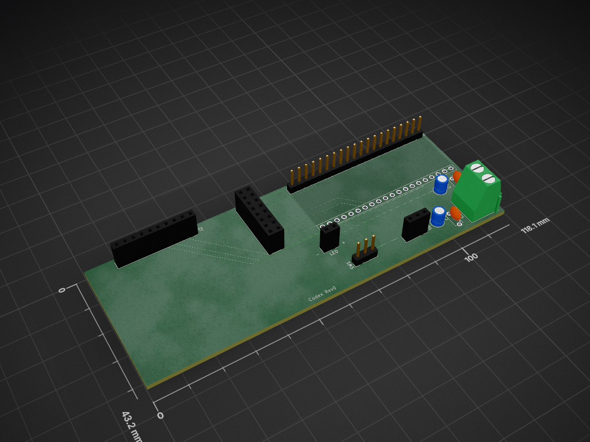
Texteditor is an open-source printed circuit board by ajackson2681, from the ajackson2681/codex repository on GitHub, published under the GPL-3.0 licence. It is a 2-layer board of 118.1 × 43.2 mm with 11 parts on 50 nets, routed with 58 tracks and 0 vias.
It is built around the L7805. Its parts include 4 capacitors, 3 connectors, 2 ICs and 1 switch.
The Codex is an attempt at an open-source, distraction-free writing device inspired somewhat by the AlphaSmart Neo (at least the display was). The Codex pairs a 40x4 character LCD with USB HID keyboard support, and SD card storage. For a more in-depth summary/breakdown, you can visit the page I have on my website: Codex Web Page.
Codex is under active development. Current state:
Working:
In progress / planned:
Maybes
Explicitly out of scope (for now):
| Component | Notes |
|---|---|
| Raspberry Pi Pico (RP2040) | Mounted via socket currently, likely castellated edge pads on the final PCB |
| 40x4 ST7066U character LCD | Dual controller (EN1/EN2), 4-bit mode |
| USB OTG converter | USB port for keyboard |
| SD card socket | SPI mode |
| Slide potentiometers (x2) | Contrast (to LCD V0) and brightness (to analog GPIO) |
| BC547 NPN transistor | PWM backlight switching |
| TP61090 boost converter | LiPo → 5V (Rev 2+) |
| MCP73871 charge controller | LiPo charge circuit (Rev 2+) |
| L7805 linear regulator | Bench/external power path (Rev0-Rev2, won't be on Rev3) |
| SPDT switch | Selects external 5V vs. LiPo/boost power source (Rev2 only), acts as power switch (Rev0 & Rev1) |
| LiPo cell | (Rev 2+) |
| Rev | Purpose | Status |
|---|---|---|
| Breadboard | Initial validation: LCD, USB host, SD card | Done |
| Rev 0 | First PCB, puts the breadboard on a dedicated PCB, adds a power switch, adds filtering capacitors | Done |
| Rev 1 | Fixes mistakes from Rev0. Sill uses socketed footprints for SD card and Pico. Adds breakout pins for contrast/brightness potentiometers, adds PWM backlight transistor. | Validating |
| Rev 2 | Dedicated SD card slot, finalized sockets for IDC, potentiometers, and LED power. Pico footprint will allow sockets or solder directly via castellated holes. 5v linear regulator will remain, with an optional switch for swapping to using a 5v direct power source (planned as a Powerboost 1000 module). | Designing |
| Rev 3 | Removal of 5v linear regulator. Move to all SMD components for assembly by fab house. | Planned |
| ??? | Anything beyond Rev3 will only happen if I make dumb mistakes (and I probably will). |
Built with the Raspberry Pi Pico SDK
If a firmware update fails or the device won't boot, hold BOOTSEL while connecting the Pico to a computer via USB. It will appear as a USB mass storage device. Then drag and drop a known-good .uf2 to restore it. This is a hardware bootloader built into the RP2040 and cannot be bricked by firmware alone.
Designed in FreeCAD. It has a sort of wedge factor with the 40x4 LCD forming most of the angled top face. Slide potentiometers for brightness and contrast are mounted on the front, with the the keyboard USB port and SD card slot to the right of those. FCStd files are located 3dmodels/ (I'm just committing the whole blob since I don't really know a better way to do it for freecad files in git).

The Codex should work with any standard USB HID keyboard, both wired or via a wireless USB dongle. The Codex does not support bluetooth keyboards.
For a compact keyboard, a 65% or 75% layout is recommended for dedicated Home/End/Page Up/Page Down/Arrow keys without needing Fn combinations. Otherwise, pretty much whatever you're most comfortable with. I use an Epomaker TH80SE, which is a 75% keyboard. However, that doesn't have a dedicated "End" key (it's FN+PgDown). Something like the Epomaker x Aula F65 or Epomaker x Aula F75 could maybe be good choices that include all the buttons.
| Shortcut | Primary Action | Secondary Action |
|---|---|---|
| Arrow keys | Move cursor (character / line) | |
| Ctrl + ←/→ | Move by word | |
| Ctrl + ↑/↓ | Jump to start/end of frame | Shift view by one full frame if at frame boundaries |
| Page Up/Page Down | Shift view by one full frame | |
| Home / End | Start/end of current line | |
| Ctrl + Home/End | Jump to start/end of current frame | |
| Ctrl + Shift + Home/End | Jump to start/end of document | |
| Tab | Insert two spaces | |
| Ctrl + S | Save current document to SD card | |
| Ctrl + Shift + I | Open document info (filename, size, etc) |
The Codex uses a split-license approach:
pcb/) and Enclosures (3dmodels/): CERN-OHL-S v2All third-party libraries retain their original licensing:
See the LICENSE file in each directory for full text.
The Codex is a work in progress and a personal project, but issues, ideas, and pull requests are welcome. If you build one, I'd love to hear about it.
| Qty | Value | Footprint | References |
|---|---|---|---|
| 2 | 100nF | Capacitor_THT:C_Disc_D4.7mm_W2.5mm_P5.00mm | C2, C3 |
| 2 | 10uF | Capacitor_THT:C_Radial_D4.0mm_H5.0mm_P1.50mm | C1, C4 |
| 1 | Conn_02x08_Odd_Even | pico:pico_idc_connector | J1 |
| 1 | L7805 | Connector_PinSocket_2.54mm:PinSocket_1x03_P2.54mm_Vertical | U2 |
| 1 | LED | Connector_PinSocket_2.54mm:PinSocket_1x02_P2.54mm_Vertical | LED |
| 1 | SD_Module | pico:SD_Module | J2 |
| 1 | SW_SPDT | Connector_PinHeader_2.54mm:PinHeader_1x03_P2.54mm_Vertical | SW1 |
| 1 | Screw_Terminal_01x02 | TerminalBlock_Phoenix:TerminalBlock_Phoenix_MKDS-1,5-2-5.08_1x02_P5.08mm_Horizontal | J3 |
| 1 | ~ | pico:pico_2x20 | U1 |
It measures 118.1 × 43.2 mm and has 2 copper layers, 1.6 mm thick.
11 parts, built around the L7805. The full list of its parts is on this page, with links to each part's symbol and footprint where PCBKit's library has them.
From the ajackson2681/codex repository on GitHub, at the commit this page was made from: the board is pcb/rev0/texteditor.kicad_pcb and its schematic pcb/pot_module/potentiometer.kicad_sch. PCBKit opens the board in the browser, with nothing to install.
Its repository publishes it under the GPL-3.0 licence: you may reuse it on that licence's terms (keep the author's notice, and for a copyleft licence share your changes alike).
ajackson2681/codex
The Codex is an attempt at an open-source, distraction-free writing device inspired somewhat by the AlphaSmart Neo (at least the display was).

ajackson2681/codex
The Codex is an attempt at an open-source, distraction-free writing device inspired somewhat by the AlphaSmart Neo (at least the display was).

ajackson2681/codex
The Codex is an attempt at an open-source, distraction-free writing device inspired somewhat by the AlphaSmart Neo (at least the display was).

ajackson2681/codex
The Codex is an attempt at an open-source, distraction-free writing device inspired somewhat by the AlphaSmart Neo (at least the display was).

Allen-Synthesis/EuroPi
EuroPi: A reprogrammable Eurorack module based on the Raspberry Pi Pico

peterheinrich/InternetOverSpaghetti
Transmitting IP packages over a pair of spaghetti thus demonstrating how media independent IP really is.


Tircown/ERCF-easy-brd
More informations on how to reset for flashing:\ https://wiki.seeedstudio.com/Seeeduino-XIAO/#enter-bootloader-mode

matthewcieplak/super-sixteen
Code and schematics for the Super Sixteen Eurorack sequencer

NikodemBartnik/Mini-Mars-Rover
Educational robotic platform made to look like a mini mars rover

starlightk7/OpenSFC
OSHW Reproduction Parts related to the Super Famicom / Super Nintendo game console

Redherring32/OpenTendo-TopLoader
An Open Source HardWare (OSHW) recreation of the 1993 toploading NES motherboard (Also known as NES-101)