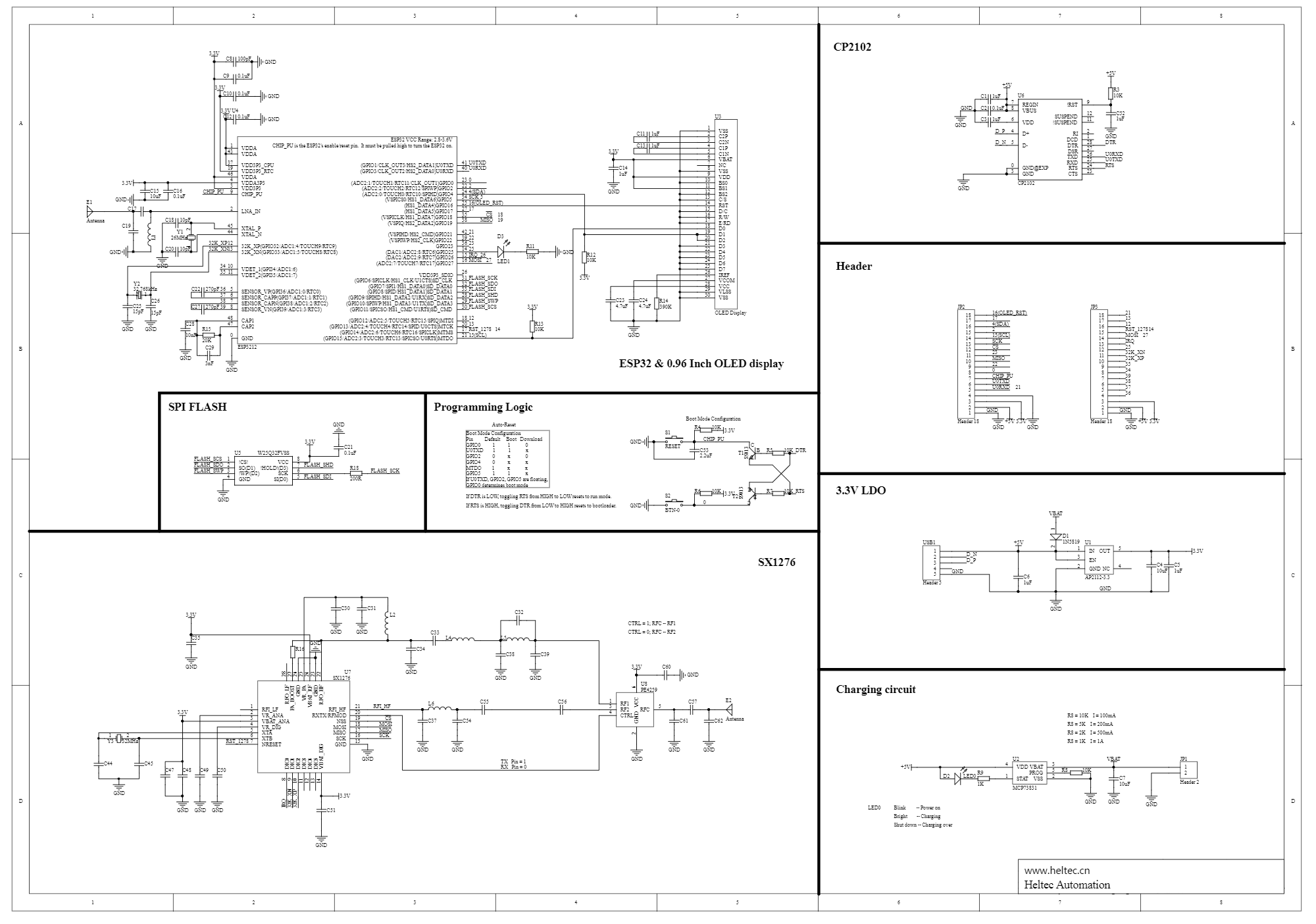
2 layers107 × 39.5 mm
 agweimar/hackTM5
Github repository for HackTM 2018
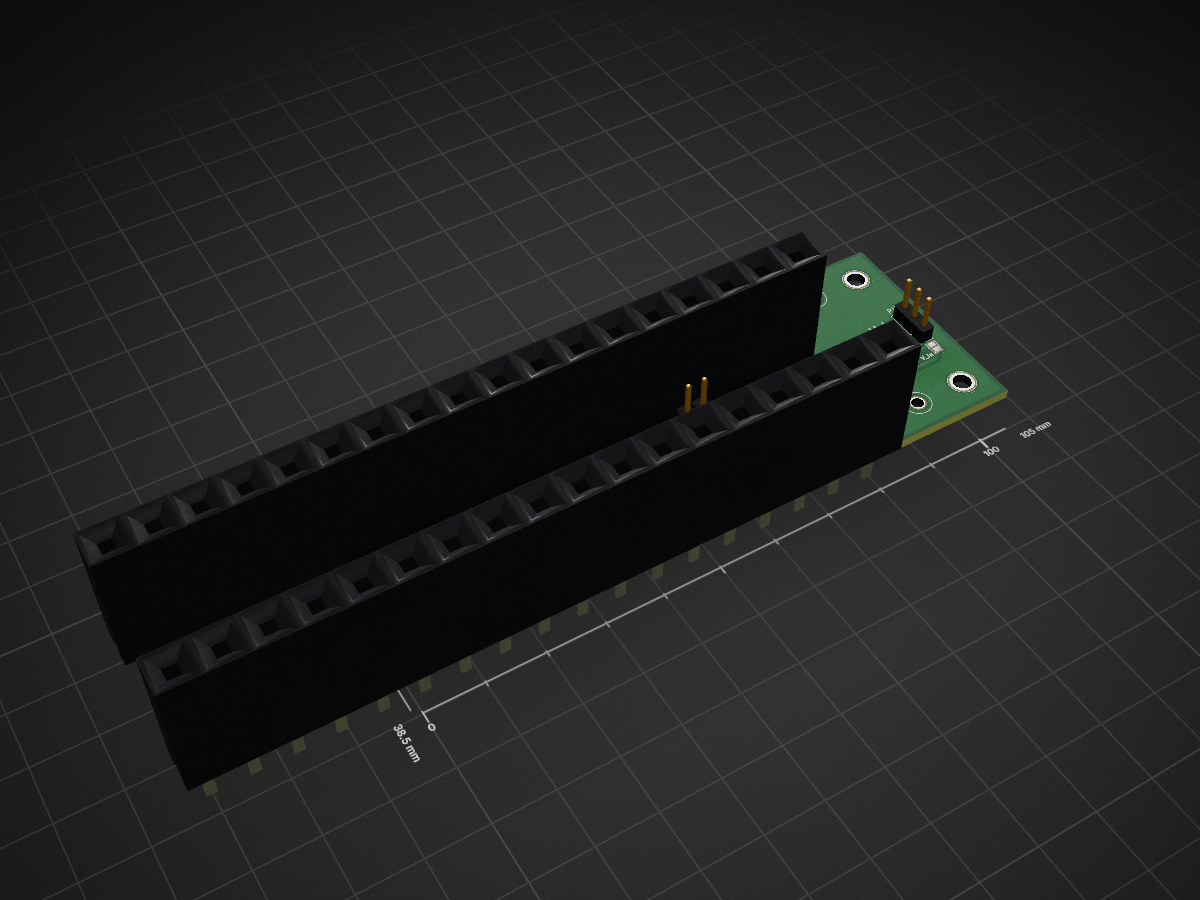
HackTM is an open-source printed circuit board by agweimar, from the agweimar/hackTM repository on GitHub, published under the GPL-3.0 licence. It is a 2-layer board of 105 × 38.5 mm with 28 parts on 39 nets, routed with 133 tracks and 5 vias.
It is built around the LM1117-1.8 and BSS138. Its parts include 12 connectors, 4 resistors, 2 transistors, 1 capacitor and 1 IC. It belongs with the power boards and the ESP32 boards of this library.


The sensor board/shield holds three major components, namely:
A top view of the board is shown below:
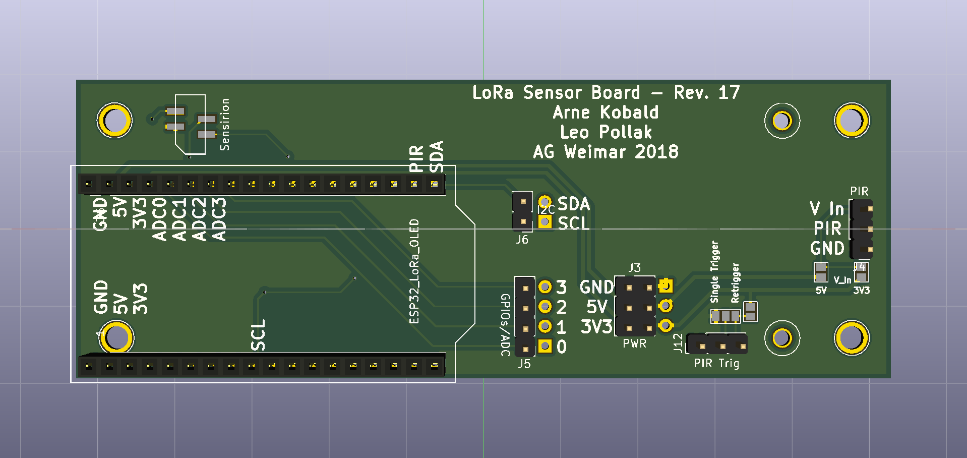
The ESP32 breakout board is put in the socket on the lower left of the board. The usb port is facing outwards, so the board can be powered from an external (USB) power supply.
On the bottom side of the ESP32 board a small LiPo battery can be connected. Charging this battery takes place via the USB port.
Caution: When booting or running the board the LoRa antenna must be connected!
Schematic
Pinout
The flex cable is put in the FFC socket above the ESP32 board. It is to be mounted in such a fashion, that the sensors face upwards when the cable is bent to the right (parallel to the ESP32 board).
The flex cable combines the Sensirion SHTC1 and SGP30. Both of the sensors are accessed via I2C. The former is a sensor for relative humidity and temperature, the latter a multipixle gas sensor.
For both sensors a convenient micropython driver can be found in the micropython directory.
The SGP30 can give raw readings corresponding to an Ethanol (EtOH) and Hydrogen (H2) signal. However, this chip can do more! If an In-Air-Qualitiy measurement has been initialized, the raw signals are used to calculate
the a TVOC signal (total volatile organic compounds) and an CO2 equivalent (CO2eq). These values already underly a dynamic baseline correction performed on-chip. To ensure these corrections works properly, it is advised to perform an iaq measurement once per second.
The power consumption of the chip can be drastically minimized by soft resetting it. This is done by an i2c general call. Caution is adviced, since other i2c devices might respont to this call as well. After each reset (hard or soft) the sensor starts in idle or sleep mode with lower power consumption. If a new iaq measurement is of intereset it needs to be initialized first,
otherwise the default values are CO2eq = 400 and TVOC = 0.
For additional information see the below datasheet.
SGP30 Datasheet
The SHTC1 sensor is a little simpler than the SGP30. It gives values for temperature and relative humidity. The sensor can be soft reseted, but doesn't have a sleep mode due to its already low power consumption.
SHTC1 Datasheet
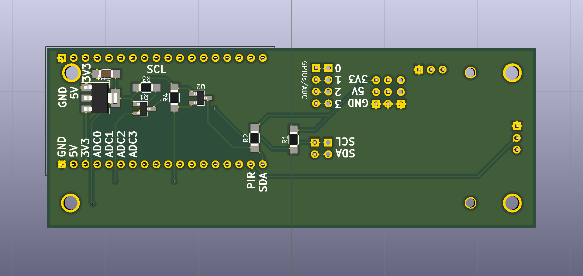
Side note: The Sensirion sensors are powered with 1.8V. The electrical components taking care of voltage generation and conversion (for the I2C bus, including 10k pull-up resistors) are situated on the bottom side of the sensor board - see picture below:
The PIR sensor is placed on the right side of the sensor board. It produces a digital Signal (logic high) whenever a motion was detected. The sensor is internally powered by 3.3V. This voltage is generated on the PIR board by a voltage regulator.
The solder jumper labeled 'V_In' on the right side selects the input voltage - either 5V or 3.3V. Keep in mind that the 5V is only 'stable' when powered via USB.
Another (prefered and thus default) way to power the PIR Board is the second socket strip on the lower side. Originally those pins are designed to select the trigger mode (explained later). However, the outer two pins are connected to ground and 3.3V of the PIR sensor.
This enables the option to surpass the PIR's voltage regulator and save energy by directly supplying 3.3V.
Via the solder jumpers labelled 'Single Trigger' and 'Retrigger' it can be selected if retriggering is possible. Retriggering is the possibility of increasing the duration of the digital output signal, when additional motion(s) are detected.
If 'Single Trigger' is selected the output signal will return to its default state () when a certain time has passed after detecting the first motion. Only now new motions cann trigger the sensor. The pulse length of the output signal can be selected with the left (when mounted upper) trimmable potentiometer.
The right (when mounted lower) potentiometer adjusts the sensitivity of the PIR sensor.
Example Datasheet
Trigger Explanation
In addition to the previously mentioned features extra pins can be found on the sensor board. These are broken out pins (as well as solder eyelets) to conveniently expand the board. They include the power pins (5V, 3.3V and GND - 5V may be limited to USB use) as well as the I2C pins SDA and SCL (3.3V level). Furthermore 4 GPIOs are broken out. Those can be used for a wide variety of scenarios. All of them can be configured via software to be digital or analogue for different I/O devices. These pins could also be used as an SPI bus.
The ESP32 can be programmed using the Ardunio IDE, the Internet-of-Things Framework from Espressif or using Micropython. We chose Micropython, because it is very easy to start with and the code is very readable even for coders that are new to python. Of course you can use your favourite IDE or even a simple text editor to code. However, below are a few suggestions of tools, that could make your life much easier.
In order to start with changing the sources for your needs, start looking in micropython
You can copy files to and from the board using different libaries:
mpy-utils establishes a Filesystem in userspace connection to the board and allow you to change files directly on the board. (very handy)bla doesn't work on Windows
ampy is used to interact with your esp32 board via serial connection.
Atom can be used with the Pymakr Plugin (see here for help). Now you can use the powerful REPL (Read-Evaluate-Print-Loop), which greatly helps while debubbing or prototyping. You can also run a pre-written script with just a click of a button (without uploading first).
esptool is needed for flashing your esp32 with new firmware.
| Qty | Value | Footprint | References |
|---|---|---|---|
| 4 | 10k | Resistors_SMD:R_1206_HandSoldering | R1, R2, R3, R4 |
| 3 | GS2 | Connectors:GS2 | J1, J2, J11 |
| 2 | 1pin | Connectors:1pin | , |
| 2 | BSS138 | TO_SOT_Packages_SMD:SOT-23_Handsoldering | Q1, Q2 |
| 2 | GPIOs/ADCs | Pin_Headers:Pin_Header_Straight_1x04_Pitch2.54mm | J5, J7 |
| 2 | I2C | Pin_Headers:Pin_Header_Straight_1x02_Pitch2.54mm | J6, J8 |
| 1 | C_Small | Capacitors_SMD:C_1206_HandSoldering | C1 |
| 1 | ESP32_LoRa_OLED | ESP32_LoRa:ESP32_LoRa | ESP_1 |
| 1 | GS3 | Connectors:GS3 | J10 |
| 1 | LM1117-1.8 | TO_SOT_Packages_SMD:SOT-223-3_TabPin2 | U1 |
| 1 | PIR | Pin_Headers:Pin_Header_Straight_1x03_Pitch2.54mm | J4 |
| 1 | PIR Trig | Pin_Headers:Pin_Header_Straight_1x03_Pitch2.54mm | J12 |
| 1 | PWR | ESP32_LoRa:PWR | J3 |
| 1 | PWR | Socket_Strips:Socket_Strip_Straight_1x03_Pitch2.54mm | J9 |
| 1 | Sensirion | ESP32_LoRa:FFC Molex | S1 |
The 24 most common of 28 parts.
It measures 105 × 38.5 mm and has 2 copper layers, 1.6 mm thick.
28 parts, built around the LM1117-1.8 and BSS138. The full list of its parts is on this page, with links to each part's symbol and footprint where PCBKit's library has them.
From the agweimar/hackTM repository on GitHub, at the commit this page was made from: the board is pcb/V3.kicad_pcb. PCBKit opens the board in the browser, with nothing to install.
Its repository publishes it under the GPL-3.0 licence: you may reuse it on that licence's terms (keep the author's notice, and for a copyleft licence share your changes alike).

karawin/Ka-Radio
A wifi webradio with only low cost boards ESP8266 and VS1053 by Jp Cocatrix


SRiegle2020/ECE49022_SrDsgn_f22_Team44
ECE49022, Team44, f2022. Biometric "Smart" Watch