2 layers206.5 × 70.5 mm
AFF314MODKEEB
Aff314/AFF314MODKEEB
AFF314MODKEEB is a 4x12 lowprofile keyboard. What makes it special are its modules. You can attach modules on top or on the right side.
103 partsCC0-1.0

 Aff314/AFF314MODKEEB
AFF314MODKEEB is a 4x12 lowprofile keyboard. What makes it special are its modules. You can attach modules on top or on the right side.
Module top1 is an open-source printed circuit board by Aff314, from the Aff314/AFF314MODKEEB repository on GitHub, published under the CC0-1.0 licence. It is a 2-layer board of 207.5 × 20.5 mm with 29 parts on 25 nets, routed with 158 tracks and 2 vias.
Its parts include 12 diodes and 12 switches. It belongs with the keyboards and input boards of this library.
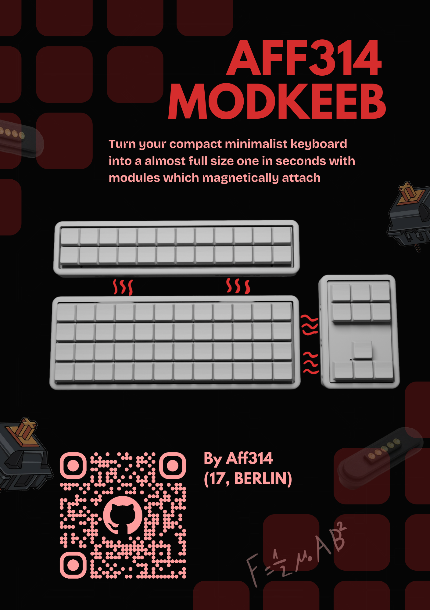
AFF314MODKEEB is a 4x12 lowprofile keyboard. What makes it special are its modules. You can attach modules on top or on the right side which are connected then connected with magnets.
I had the idea because I daily drive 40% and 75% keyboards. I wanted to have one keyboard which can be used for both. With this keyboard you can have a full sized keyboard with number-keys, f-keys and arrow keys if you need it for a game or programm. But if you want to have a more minimal keyboard you can just detach the modules and have a nice and compact 40% keyboard.
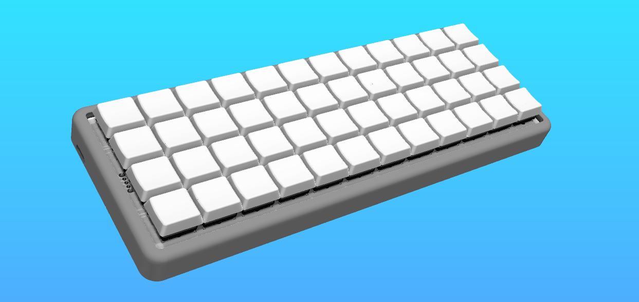
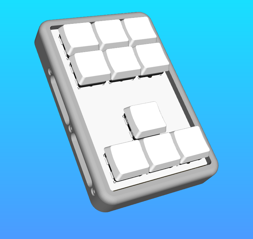
You can attach the modules on top and on the right side. So far I have designed three modules.
One for the right side. It has arrow-keys plus six extra keys that can be used for what ever you like.
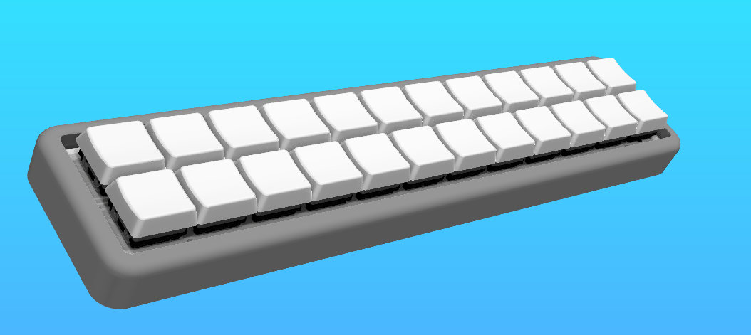
The two that go on top are either a number or f-key row or a number plus f-key module. I decided to only order the pcbs for the number plus f-key module since you can type the numbers and f-keys also with layers so when I really need the f-keys or numbers the others don't hurt and it would take away from that convenience I wanted if you have so many modules laying around.
If you want to you can design your own modules. You can use the same cases I designed and you have to modify the pcbs.
If you want to build the keyboard you have to not only solder on the pcb but also solder some wires. Once the keyboard is built I will add pictures for better understanding.
To flash the firmware you have to download the UF2 file.
On the pcbs you first have to solder on all the diodes and hotswap sockets. Then you can solder on the power switch if you want to use one, because you can also use it without a powerswitch and solder the battery directly or just use it wired.
Before we wire everything we need the prepare the connectors. For this you need to print the mounting bracktets. Then you can melt the heat inserts in the mounting bracket and attach it to the magnetic connector.
We also need to prepare the case. This is pretty straight forward as you only need to add the heat inserts.
We will start with the magnetic connectors we have prepared. We need to wire the cables to the pins. It is probably a good idea to use heat shrink tubing to isolate the exposed pins right by eachother but you dont have to. Once the wires are soldered to them we take them and mount them inside the case. Look at the schematics and at the wiring_guides for help.
You can wire them to the mcu now. You also need to wire the rows and columns from the pcb to the mcu. For this you can take a look at the pcb but I will also add pictures once it's build. At last you can wire the battery.
The nice nano or if built wired the rp2040 will fit perfectly in the cutout for it in the bottom of the case. Optionaly you could glue it in place but it will also hold on its own so there is no need fo it unless you want the most secure fit.
I made this keyboard for fallout from hackclub and they give the chance for you to show off your project in a magazine. This is my page for zine. I will change it once I've built it irl because the real pictures would make it look way better.
| Qty | Value | Footprint | References |
|---|---|---|---|
| 12 | D | AFFElib:Diode_SOD123 | D1, D2, D3, D4, D5, D6, D7, D8, D9, D10, D11, D12 |
| 12 | SW_Push_45deg | AFFElib:choc_16 | SW1, SW2, SW3, SW4, SW5, SW6, SW7, SW8, SW9, SW10, SW11, SW12 |
The 24 most common of 29 parts.
It measures 207.5 × 20.5 mm and has 2 copper layers, 1.6 mm thick.
29 parts. The full list of its parts is on this page, with links to each part's symbol and footprint where PCBKit's library has them.
From the Aff314/AFF314MODKEEB repository on GitHub, at the commit this page was made from: the board is pcb/top1/module_top1.kicad_pcb and its schematic pcb/main/AFF314MODKEEB.kicad_sch. PCBKit opens the board in the browser, with nothing to install.
Its repository publishes it under the CC0-1.0 licence: you may reuse it on that licence's terms (keep the author's notice, and for a copyleft licence share your changes alike).
Aff314/AFF314MODKEEB
AFF314MODKEEB is a 4x12 lowprofile keyboard. What makes it special are its modules. You can attach modules on top or on the right side.

Aff314/AFF314MODKEEB
AFF314MODKEEB is a 4x12 lowprofile keyboard. What makes it special are its modules. You can attach modules on top or on the right side.

Aff314/AFF314MODKEEB
AFF314MODKEEB is a 4x12 lowprofile keyboard. What makes it special are its modules. You can attach modules on top or on the right side.

gusmanb/logicanalyzer
24 channel, 100Msps logic analyzer hardware and software

VoronDesign/Voron-Hardware
Cool Hardware designed by the Voron Design group

hoglet67/RGBtoHDMI
Bare-metal Raspberry Pi project that provides pixel-perfect sampling of Retro Computer RGB/YUV video and conversion to HDMI

hackclub/OnBoard
💡 Join 1,000 teenagers and make your first PCB with a $100 grant!

OLIMEX/DIY-LAPTOP
Do It Yourself Open Source Hardware and Software Modular Hacker's Friendly Laptop

UtilitechAS/amsreader-firmware
ESP8266 and ESP32 compatible firmware to read, interpret and publish data to MQTT from smart electrical meters, both DLMS and DSMR is supported

