

4 layers94 × 43 mm
DmxTx
microchip-pic-avr-examples/pic16f56q71-audio-light-show-mplab-mcc
An audio-reactive light show driven by the Q71's analog and DMX capabilities.
73 parts8

 afcaff/opamp-amp
Audio preamp with adjustable gain and Baxandall bass/treble tone control, built on a TL072 with a 15V single supply.
Audiopamp is an open-source printed circuit board by afcaff, from the afcaff/opamp-amp repository on GitHub. It is a 2-layer board of 100 × 59.5 mm with 29 parts on 23 nets, routed with 132 tracks and 1 via.
It is built around the TL072 and STX-3000. Its parts include 3 connectors, 2 capacitors, 2 resistors, 2 ICs and 1 diode. It belongs with the audio and music boards of this library.
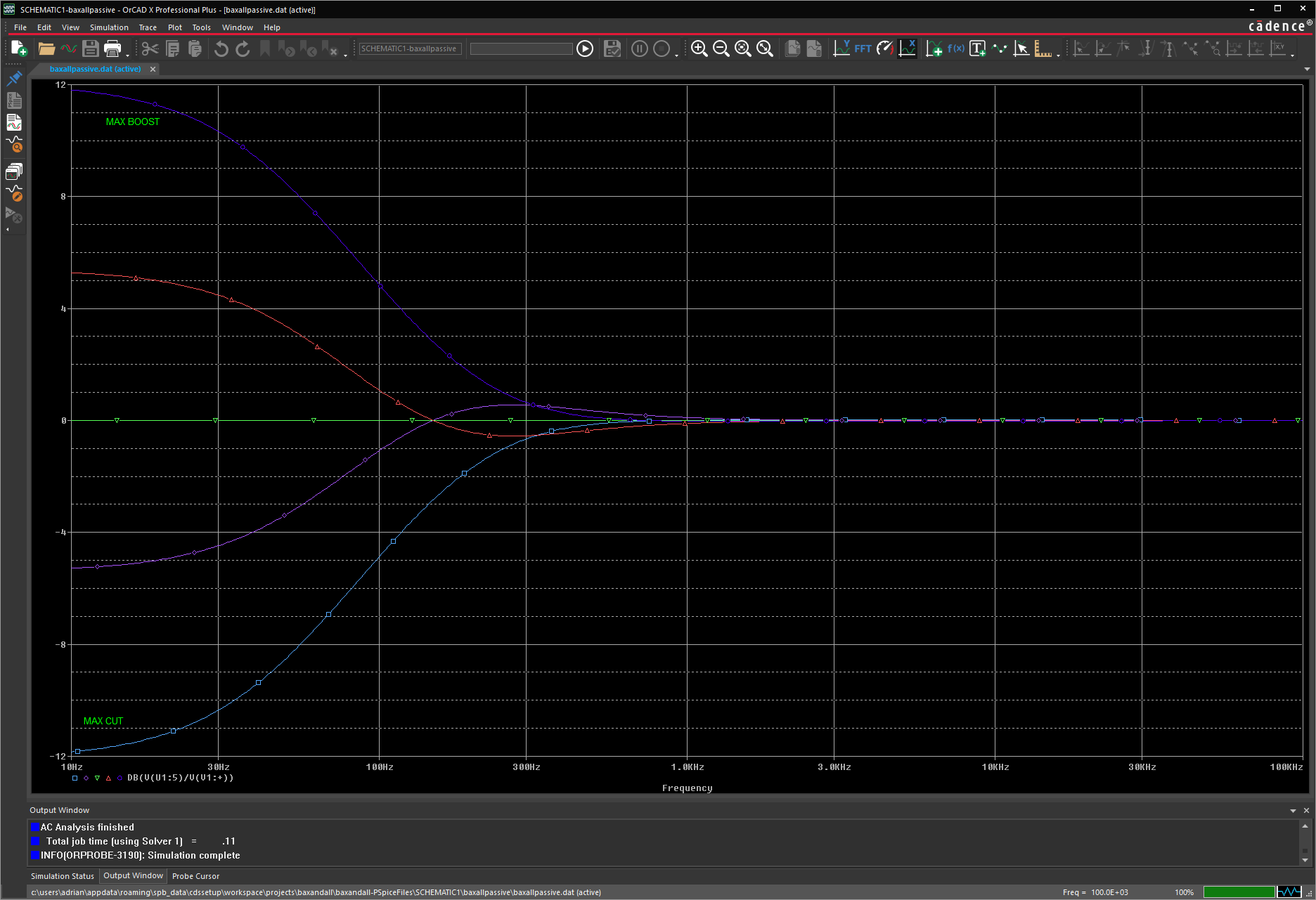
Single-channel audio preamp with gain, bass and treble controls, built around a TL072. I simulated it in PSpice, built it on a breadboard, then laid out a PCB in KiCad and measured both.
A phone or laptop plugs into the input and the output goes to a powered speaker. The gain knob turns the signal up to about 10x, and the bass and treble knobs boost or cut by about 12 dB.
https://github.com/user-attachments/assets/7785a830-bcad-4880-86f1-33a1208d45af
https://github.com/user-attachments/assets/1d51f3fe-2df7-4398-9d68-10ba9ee7a141
Labeled Circuit:
| Target | Calculated | Breadboard (meter) | PCB (meter) | PCB (scope) | |
|---|---|---|---|---|---|
| Gain | 0 to 20 dB | 0 to 20.8 dB* | 0 to 21.4 dB | 0 to 19.7 dB | 0 to 19.6 dB |
| Flat response (both tone pots centered, 400 Hz) | ±1 dB | 0 dB | +0.6 dB | −0.3 dB | 0 dB |
| Bass at 50 Hz | ±12 dB | +8.2 / −8.2 dB | +8.3 / −8.5 dB | +8.1 / −8.3 dB | +8.3 / −8.1 dB |
| Treble at 10 kHz | ±12 dB | +11.2 / −11.2 dB | +11.8 / −12.5 dB | +12.2 / −12.4 dB | +11.4 / cut failed (pot) |
| Virtual ground | 7.5 V | 7.5 V | 7.48 V | 7.38 V | — |
The first half of the TL072 is a non-inverting amp. RG is 10k and RF is a 100k pot, so the gain goes from 1 (0 dB) to 11 (20.8 dB). CG (47µF) in series with RG keeps the DC gain at 1 so the output offset stays small.
The second half is a Baxandall tone control. A lot of published versions use 10k resistors around the pots, which gives around ±20 dB. I used 33k so the gain at the ends of the pot is (100k + 33k) / 33k ≈ 4, which is 12 dB.
It runs on a single 15 V supply. The TLE2426 makes a 7.5 V virtual ground so the op amps can swing both ways around it.
Hand calculations: measure/HandCalcs.pdf
Full circuit simulation: FullCircuitsim/
After verifying everything on the breadboard, I designed a two layer board in KiCad. Every part is through-hole and designed for hand soldering. The pots and audio jacks mount directly to the board.
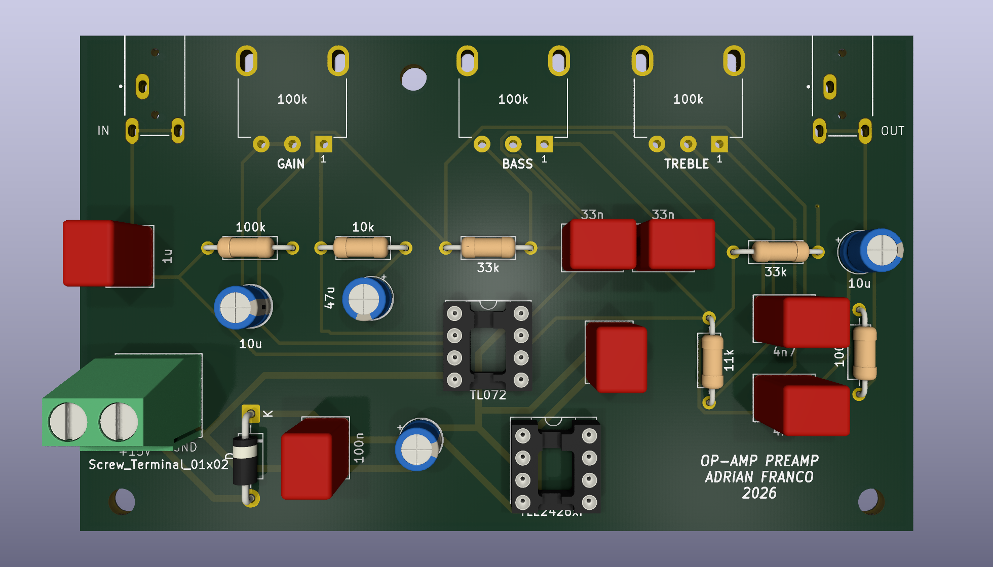
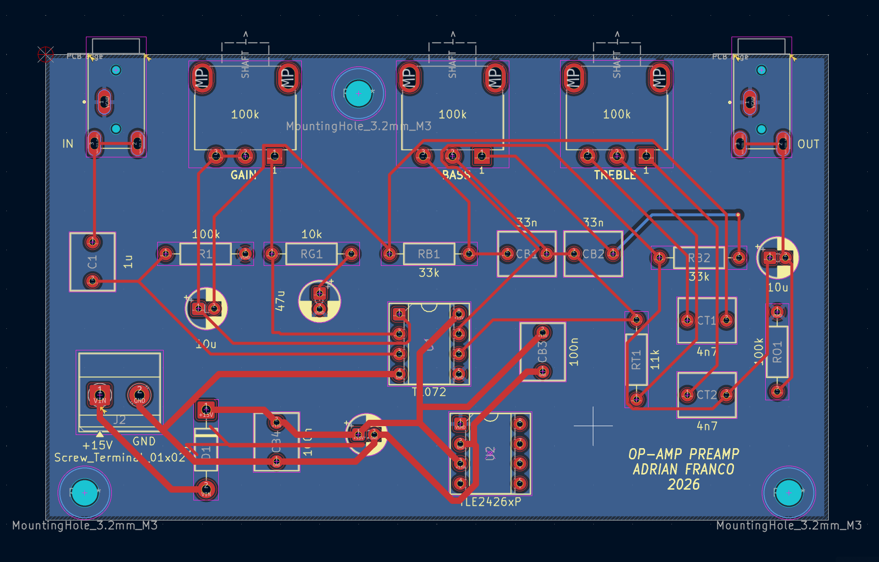 Finished PCB:
Schematic: docs/PrintUSchematic.pdf
| Item | Value |
|---|---|
| Size | about 100 × 60 mm |
| Layers | 2 (signals on top, VGround on bottom) |
| Parts | through-hole, TL072 and TLE2426 in DIP-8 sockets |
| Power input | 2 pin screw terminal, 15 V, with a series diode |
| Decoupling | 100 µF + 100 nF at the supply input, 100 nF next to the TL072 |
| Traces | 0.4 mm signal, 0.8 mm power |
| Mounting | M3 holes for standoffs |
| Gain pot | In (V) | Out (V) | Gain | dB | Scope (dB) | Calculated (dB) |
|---|---|---|---|---|---|---|
| Min | 0.097 | 0.096 | 0.99x | −0.1 | −0.1 | 0 |
| Half | 0.097 | 0.541 | 5.6x | 14.9 | 14.7 | 14.5 |
| Max | 0.097 | 0.941 | 9.7x | 19.7 | 19.6 | 19.7 |
Bass at 50 Hz:
| Bass pot | In (V) | Out (V) | Gain | dB | Scope (dB) |
|---|---|---|---|---|---|
| Full cut | 0.119 | 0.046 | 0.39x | −8.3 | −8.1 |
| Center | 0.119 | 0.120 | 1.01x | +0.1 | +0.1 |
| Full boost | 0.119 | 0.304 | 2.55x | +8.1 | +8.3 |
Treble at 10 kHz:
| Treble pot | In (V) | Out (V) | Gain | dB | Scope (dB) |
|---|---|---|---|---|---|
| Full cut | 0.096 | 0.023 | 0.24x | −12.4 | failed (worn pot) |
| Center | 0.096 | 0.094 | 0.98x | −0.2 | +0.2 |
| Full boost | 0.096 | 0.393 | 4.09x | +12.2 | +11.4 |
measure/scopekicad/kicad/audiopamp/gerber.zipAll readings were taken with a multimeter on AC volts, black probe on the virtual ground, using sine tones from a laptop.
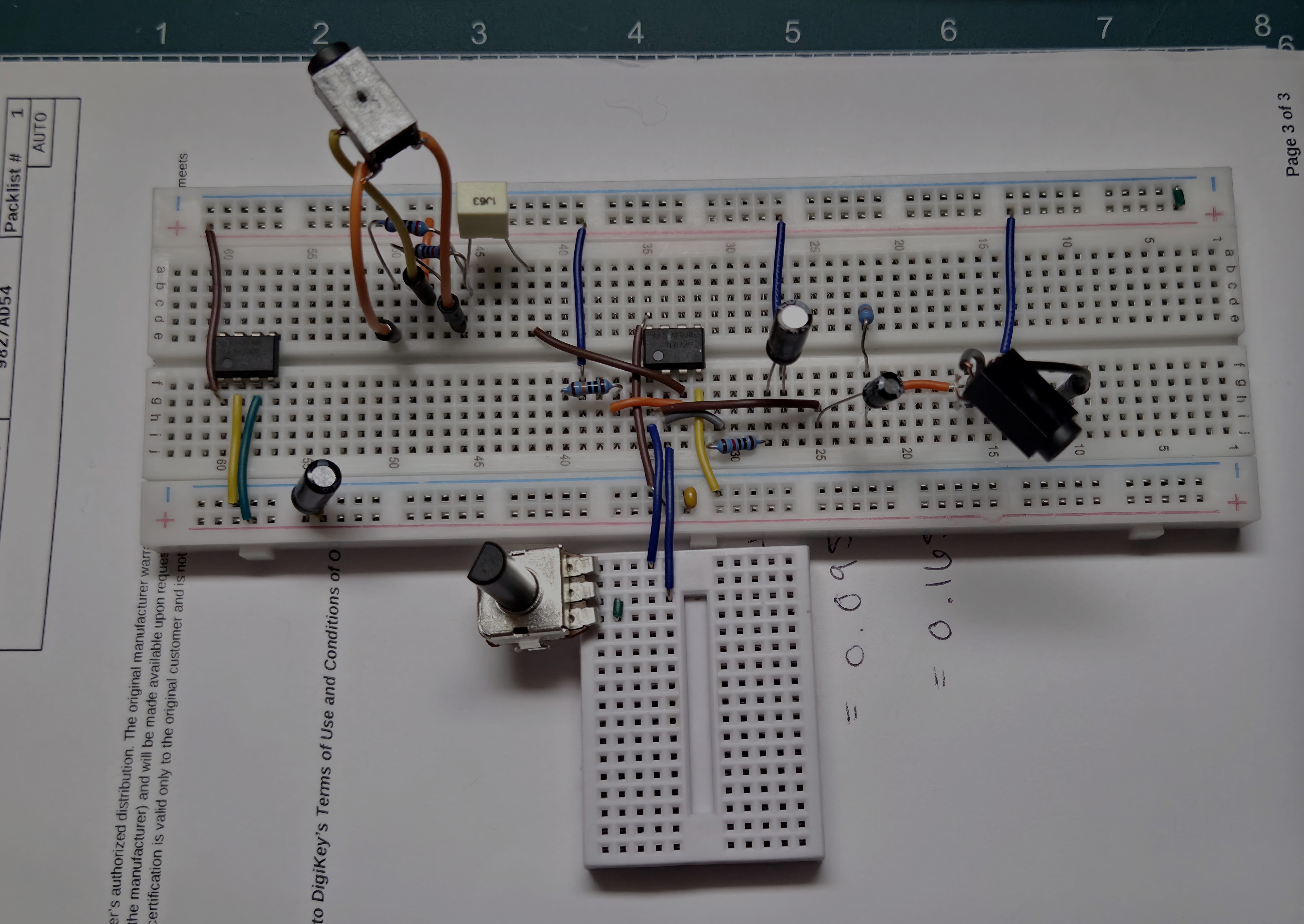
Gain stage demo:
https://github.com/user-attachments/assets/f91d0bfd-d7b4-4a68-a31d-0bf0310b4c41
| Gain pot | In (V) | Out (V) | Gain | dB | PSpice (dB) |
|---|---|---|---|---|---|
| Min | 0.014 | 0.014 | 1.0x | 0 | 0 |
| Half | 0.014 | 0.095 | 6.8x | 16.6 | 15.6 |
| Max | 0.014 | 0.165 | 11.8x | 21.4 | 20.8 |
The input was only 14 mV, which limits the meter to about ±7%, so these are within the meter's accuracy.
Gain is the tone stage output (pin 7) divided by its input.
Bass at 50 Hz:
| Bass pot | In (V) | Out (V) | Gain | dB |
|---|---|---|---|---|
| Full cut | 0.254 | 0.096 | 0.38x | −8.5 |
| Center | 0.254 | 0.245 | 0.96x | −0.3 |
| Full boost | 0.254 | 0.657 | 2.59x | +8.3 |
Treble at 10 kHz:
| Treble pot | In (V) | Out (V) | Gain | dB |
|---|---|---|---|---|
| Full cut | 0.126 | 0.030 | 0.24x | −12.5 |
| Center | 0.126 | 0.127 | 1.01x | +0.1 |
| Full boost | 0.126 | 0.491 | 3.90x | +11.8 |
At 1 kHz the bass knob does nothing (within 0.1 dB) and the treble knob moves the level by about ±1.8 dB, since the treble shelf starts around 3 kHz.
Non-inverting gain:
$$\frac{V_o}{V_i} = 1 + \frac{R_F}{R_G}$$
Gain in dB:
$$A_V[\text{dB}] = 20\log\left(\frac{V_o}{V_i}\right)$$
Filter frequency:
$$f = \frac{1}{2\pi RC}$$
PSpice, KiCad
Rod Elliott's site sound-au.com explained most of what I needed for this project.
Learn About Electronics: Baxandall tone control explains how the bass and treble controls work and what the response looks like.
This video helped me see which path each frequency takes through the tone circuit.
| Qty | Value | Footprint | References |
|---|---|---|---|
| 3 | 100k | opamp_pream:pdb12-M | RBP1, RF1, RTP1 |
| 2 | 100k | Resistor_THT:R_Axial_DIN0207_L6.3mm_D2.5mm_P10.16mm_Horizontal | R1, RO1 |
| 2 | 100n | Capacitor_THT:C_Rect_L7.2mm_W5.5mm_P5.00mm_FKS2_FKP2_MKS2_MKP2 | CB3, CB4 |
| 2 | 10u | Capacitor_THT:CP_Radial_D5.0mm_P2.00mm | CL1, CO1 |
| 2 | 33k | Resistor_THT:R_Axial_DIN0207_L6.3mm_D2.5mm_P10.16mm_Horizontal | RB1, RB2 |
| 2 | 33n | Capacitor_THT:C_Rect_L7.2mm_W5.5mm_P5.00mm_FKS2_FKP2_MKS2_MKP2 | CB1, CB2 |
| 2 | 4n7 | Capacitor_THT:C_Rect_L7.2mm_W5.5mm_P5.00mm_FKS2_FKP2_MKS2_MKP2 | CT1, CT2 |
| 2 | STX-3000 | STX-3000:KYCON_STX-3000 | J1, J3 |
| 1 | 100u | Capacitor_THT:CP_Radial_D5.0mm_P2.00mm | C2 |
| 1 | 10k | Resistor_THT:R_Axial_DIN0207_L6.3mm_D2.5mm_P10.16mm_Horizontal | RG1 |
| 1 | 11k | Resistor_THT:R_Axial_DIN0207_L6.3mm_D2.5mm_P10.16mm_Horizontal | RT1 |
| 1 | 1u | Capacitor_THT:C_Rect_L7.2mm_W5.5mm_P5.00mm_FKS2_FKP2_MKS2_MKP2 | C1 |
| 1 | 47u | Capacitor_THT:CP_Radial_D5.0mm_P2.00mm | CG1 |
| 1 | D | Diode_THT:D_DO-41_SOD81_P10.16mm_Horizontal | D1 |
| 1 | Screw_Terminal_01x02 | TerminalBlock_Phoenix:TerminalBlock_Phoenix_MKDS-1,5-2-5.08_1x02_P5.08mm_Horizontal | J2 |
| 1 | TL072 | Package_DIP:DIP-8_W7.62mm_Socket | U1 |
| 1 | TLE2426xP | Package_DIP:DIP-8_W7.62mm_Socket | U2 |
The 26 most common of 29 parts.
It measures 100 × 59.5 mm and has 2 copper layers, 1.6 mm thick.
29 parts, built around the TL072 and STX-3000. The full list of its parts is on this page, with links to each part's symbol and footprint where PCBKit's library has them.
From the afcaff/opamp-amp repository on GitHub, at the commit this page was made from: the board is kicad/audiopamp/audiopamp.kicad_pcb and its schematic kicad/audiopamp/audiopamp.kicad_sch. PCBKit opens the board in the browser, with nothing to install.
Its repository states no licence, so its author keeps all rights: ask afcaff before reusing the design.
microchip-pic-avr-examples/pic16f56q71-audio-light-show-mplab-mcc
An audio-reactive light show driven by the Q71's analog and DMX capabilities.


davw4453/Tube-Amplifier-Project
This is a vacuum tube amplifier with modular input modules to provide for different audio source methods. This project was designed for my captsone project at CCSU.

LSDRM/DualPressure-Thermocouple_forVMCGUI
A customized DAQ board through UART protocol, embeding two pressure sensors and one thermocouple. Has been developed to be used with VMCGUI.

ohmtech-rdi/eurorack-blocks
Software to Hardware Prototyping for Eurorack using C++, Max/Gen~ or Faust

ctag-fh-kiel/ctag-tbd
CTAG TBD >>to be determined<< an extendible open source Eurorack sound module

plinkysynth/plinky_public
a public release of the plinky sw and hw