2 layers100 × 100 mm

 AevumDecessus/Ergo-Nano
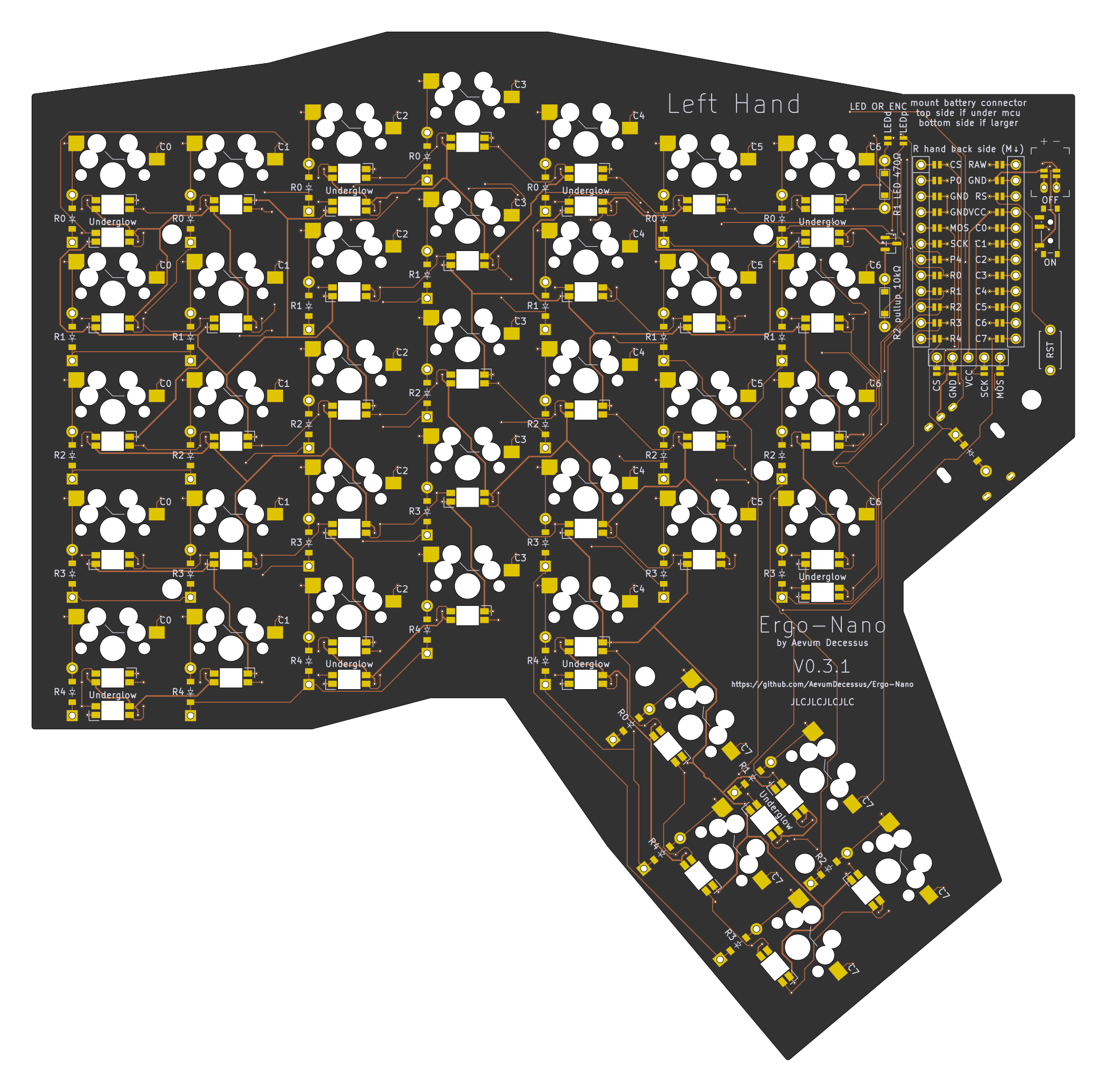
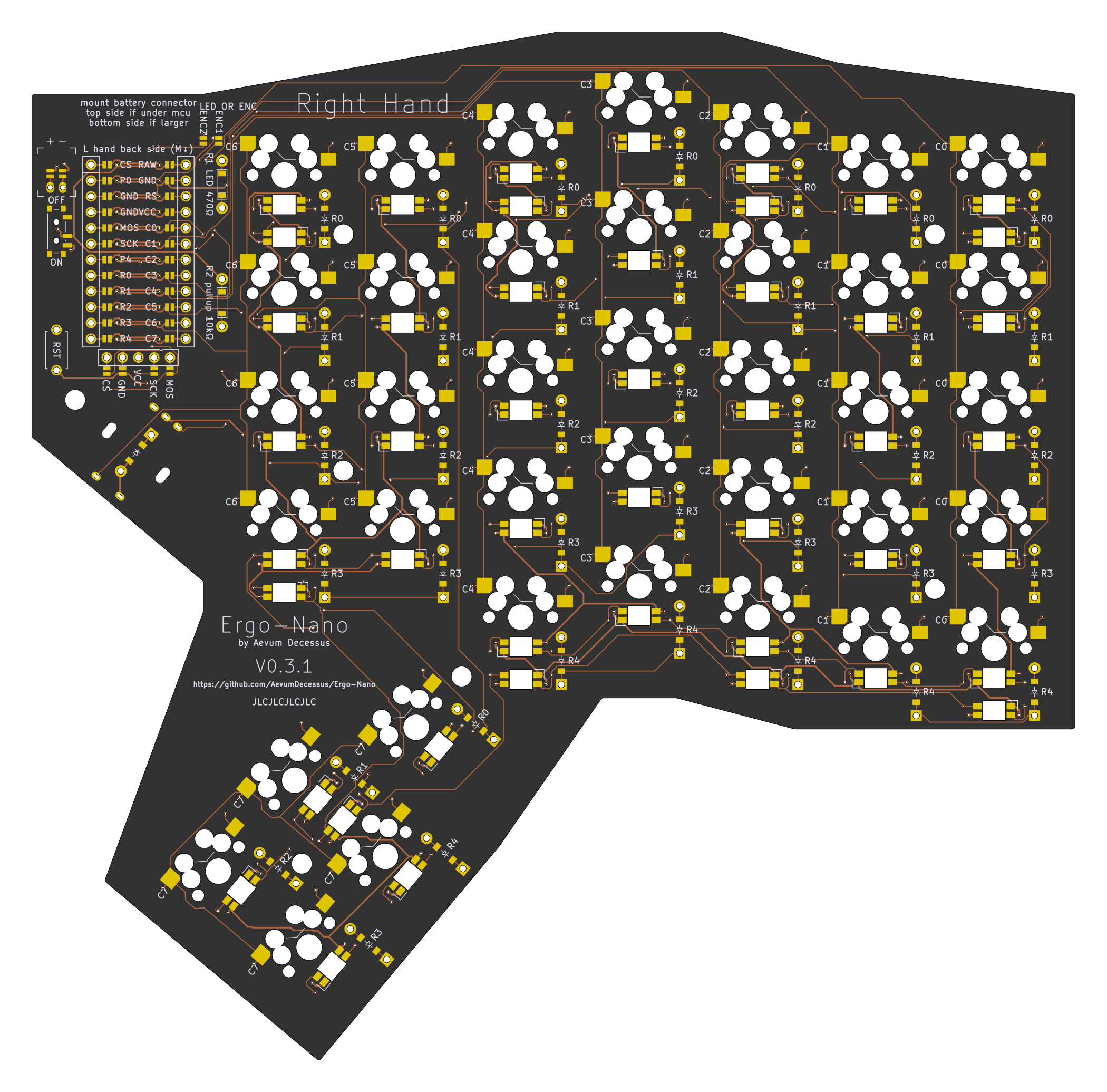
A ergodox/moonlander inspired wireless-first split keyboard design, defined in code with [Ergogen][ergogen].
Ergo Nano is an open-source printed circuit board by AevumDecessus, from the AevumDecessus/Ergo-Nano repository on GitHub, published under the MIT licence. It is a 2-layer board of 167.6 × 165.2 mm with 144 parts on 145 nets, routed with 1,645 tracks and 264 vias.
Its parts include 86 diodes, 38 switches, 4 connectors, 2 resistors and 1 transistor.
A ergodox/moonlander inspired wireless-first split keyboard design, defined in code with Ergogen.
Utilizes the nice!nano for a wireless-first methodology. The wireless firmware is built on ZMK.
This layout is fully generated, and as of the V0.1 release HAS NOT BEEN BUILT OR TESTED YET. Feel free to use this as a reference, but you are making this at your own risk until it has been build, tested, and vetted.
Replaced all the 1.5U keys with 1U keys on the farthest outside rows, moved the thumb cluster closer to the natural thumb resting location, a major complaint with the Ergodox.
Each half is a 5x6 matrix with 5 thumb keys, and the modifier keys removed from the innermost 2 columns.
Built with MX keysizes be default.
2 optional jumpers are located to the left of the MCU to choose between per-key and underglow LEDS, or the rotatry encoder located below the main board. Connect the one you would like with a solder bridge in order to enable pin P0 to connect to either the led chain din, or to one of the encoder's rotary pins (the other is connected to the pin labeled E2)
Case STLs:
Plates:
| Qty | Value | Footprint | References |
|---|---|---|---|
| 47 | ceoloide:led_SK6812mini-e (per-key, reversible) | LED1, LED2, LED10, LED11, LED12, LED13, LED14, LED15, LED16, LED17, LED18, LED19, LED20, LED21, LED22, LED23 +31 | |
| 39 | ceoloide:diode_tht_sod123 | D1, D2, D10, D11, D12, D13, D14, D15, D16, D17, D18, D19, D20, D21, D22, D23 +23 | |
| 38 | ceoloide:switch_mx | S1, S2, S10, S11, S12, S13, S14, S15, S16, S17, S18, S19, S20, S21, S22, S23 +22 | |
| 7 | ceoloide:mounting_hole_npth | MH1, MH2, MH3, MH4, MH5, MH6, MH7 | |
| 4 | ceoloide:jumper | J1, J2, J3, J4 | |
| 2 | ceoloide:resistor_tht_1206 | R1, R2 | |
| 1 | ceoloide:rotary_encoder_ec11_ec12 | RE1 | |
| 1 | ceoloide:display_nice_view | DISP1 | |
| 1 | SOT-23 | Q1 | |
| 1 | ceoloide:battery_connector_jst_ph_2 | JST1 | |
| 1 | ceoloide:power_switch_smd_side | PWR1 | |
| 1 | ceoloide:reset_switch_tht_top | RST1 | |
| 1 | ceoloide:mcu_nice_nano | MCU1 |

hackclub/OnBoard
💡 Join 1,000 teenagers and make your first PCB with a $100 grant!


rgoulter/keyboard-labs
Repo with my PCB designs and keyboard firmware


portlandhodl/nyan-keys-hardware
Hardware document for the nyan keys keyboard
It measures 167.6 × 165.2 mm and has 2 copper layers, 1.6 mm thick.
144 parts. The full list of its parts is on this page, with links to each part's symbol and footprint where PCBKit's library has them.
From the AevumDecessus/Ergo-Nano repository on GitHub, at the commit this page was made from: the board is pcbs/ergonano.kicad_pcb. PCBKit opens the board in the browser, with nothing to install.
Its repository publishes it under the MIT licence: you may reuse it on that licence's terms (keep the author's notice, and for a copyleft licence share your changes alike).