
2 layers152 × 88 mm
RFBitBangSMT
profdc9/RFBitBanger
A QRP digital transceiver created from readily available parts for off-the-grid maintenance
271 parts222

 adoble/LM386-Simple-Amplifier
Simple LM386 audio amplifier with perfboard layout in KiCad
LM386 BassBoost is an open-source printed circuit board by adoble, from the adoble/LM386-Simple-Amplifier repository on GitHub. It is a 2-layer board of 63.5 × 48.3 mm with 27 parts on 22 nets, routed with 88 tracks and 420 vias.
It is built around the LM386. Its parts include 12 capacitors, 6 resistors, 5 connectors and 2 ICs. It belongs with the audio and music boards of this library.
This is a simple LM386 based audio amplifier that I can use as a utility amplifier when dealing with audio signals. It is not really a "hifi" amplifier, but produces an acceptable sound on small loudspeakers.
The main purpose of the project though, was to do a perfboard design using KiCad. I've usually done the layout design in the past either with paper and pencil or even on the fly directly on the board. The results have not been good.
The circuit is based strongly on the design shown in Circuit Basics.
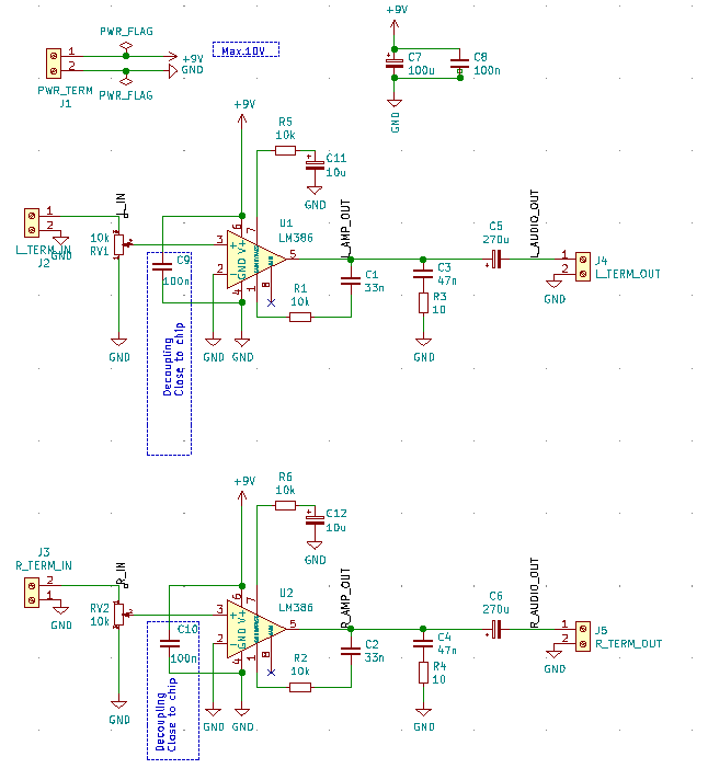
One of the main reasons for this project was to see if KiCad could be used to layout the wiring on a perfboard, i.e. soldering bare wires on the back side of the perfboard. The result is shown below:
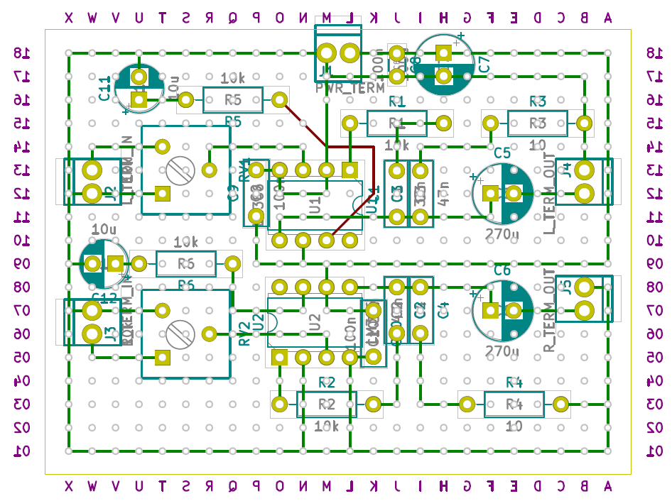
I set the grid to 2.54mm and then laid out the footprints. I then routed the pins together making sure that each track had only 90 degree turns. Finally I used to array layout function in KiCad to layout the vias. These represent the holes on the perfboard.
I tried to get all components on the front side of the board with the connections as bare wires on the back side. Unfortunately I made a couple of changes after I had soldered some of the components and wiring, meaning a planar layout I had achieved before was no longer possible. You can see that with the one red (front side) track on the layout. I used an insulated wire, again on the back side, but put some isolation tape between it and the bare wires just to be sure.
Using the KiCad PCB tool meant it was a lot easier to do a clean(er) layout than when I used paper and pencil.
| Qty | Value | Footprint | References |
|---|---|---|---|
| 4 | 10k | Resistor_THT:R_Axial_DIN0207_L6.3mm_D2.5mm_P10.16mm_Horizontal | R1, R2, R5, R6 |
| 2 | 10 | Resistor_THT:R_Axial_DIN0207_L6.3mm_D2.5mm_P10.16mm_Horizontal | R3, R4 |
| 2 | 100n | Capacitor_THT:C_Disc_D7.0mm_W2.5mm_P5.00mm | C9, C10 |
| 2 | 10k | LM386_BassBoost:Potentiometer_Trimmer_Bourns_3310Y | RV1, RV2 |
| 2 | 10u | Capacitor_THT:CP_Radial_D5.0mm_P2.50mm | C11, C12 |
| 2 | 270u | Capacitor_THT:CP_Radial_D6.3mm_P2.50mm | C5, C6 |
| 2 | 33n | Capacitor_THT:C_Disc_D7.0mm_W2.5mm_P5.00mm | C1, C2 |
| 2 | 47n | Capacitor_THT:C_Disc_D7.0mm_W2.5mm_P5.00mm | C3, C4 |
| 2 | LM386 | Package_DIP:DIP-8_W7.62mm | U1, U2 |
| 1 | 100n | Capacitor_THT:C_Disc_D3.0mm_W1.6mm_P2.50mm | C8 |
| 1 | 100u | Capacitor_THT:CP_Radial_D6.3mm_P2.50mm | C7 |
| 1 | L_TERM_IN | LM386_BassBoost:Screw_Terminal_1x02 | J2 |
| 1 | L_TERM_OUT | LM386_BassBoost:Screw_Terminal_1x02 | J4 |
| 1 | PWR_TERM | LM386_BassBoost:Screw_Terminal_1x02 | J1 |
| 1 | R_TERM_IN | LM386_BassBoost:Screw_Terminal_1x02 | J3 |
| 1 | R_TERM_OUT | LM386_BassBoost:Screw_Terminal_1x02 | J5 |
profdc9/RFBitBanger
A QRP digital transceiver created from readily available parts for off-the-grid maintenance

mattybrad/drumkid
Version 4 was the first successful working design, with full code, schematics, Gerbers, etc available on GitHub.

leomil72/LM80C
A Z80-based homebrew computer withTMS9918, AY-3-8910, Z80 CTC, Z80 PIO, and Z80 SIO


oskitone/poly555
The POLY555 is a polyphonic, analog, square wave synth based on the 555 timer chip.

robfinch/Cores
Cores ===== RTF's Cores Use at your own risk. Welcome to my galaxy of cores. Contained in the directories are IP cores, source code for digital circuits.


It measures 63.5 × 48.3 mm and has 2 copper layers, 1.6 mm thick.
27 parts, built around the LM386. The full list of its parts is on this page, with links to each part's symbol and footprint where PCBKit's library has them.
From the adoble/LM386-Simple-Amplifier repository on GitHub, at the commit this page was made from: the board is LM386_BassBoost.kicad_pcb. PCBKit opens the board in the browser, with nothing to install.
Its repository states no licence, so its author keeps all rights: ask adoble before reusing the design.