This Repo will follow me while i m impelmenting a flight controller using stm32 blue pill board. I will be using the following components: - STM32F103C8T6 (Blue Pill) - MPU6050 (Gyro and Accelerometer) - IA6S (Receiver)…
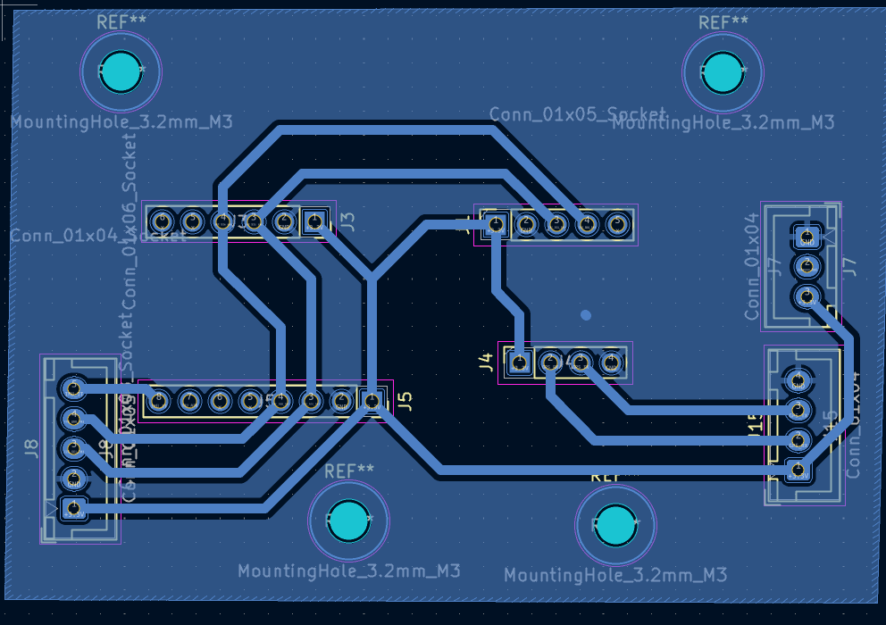
Flight controller is an open-source printed circuit board by ademda, from the ademda/Drone_Flight_Controller repository on GitHub. It is a 2-layer board with 17 parts on 67 nets, routed with 97 tracks and 0 vias.
Its parts include 9 connectors, 2 resistors, 1 capacitor and 1 IC. It belongs with the robots and motor control boards of this library.
README
Readme.md
This Repo will follow me while i m impelmenting a flight controller using stm32 blue pill board. I will be using the following components:
STM32F103C8T6 (Blue Pill)
MPU6050 (Gyro and Accelerometer)
IA6S (Receiver)
Flysky FS-iA6B (Transmitter)
bmp280 (Barometer)
HMC5883L (Magnetometer)
ESCS (Electronic Speed Controllers)
Brushless Motors
Neo6m (GPS)
the first version should be capable of flying a quadcopter and maintain its position in the air:
I would try my best to make the code as modular as possible so that it can be easily modified and extended in the future. I will be using OOp based design patterns to ensure the modularity, so the code will contain both C and C++
Software architecture will be based on the layered architecture pattern, where each layer will have a specific responsibility and will communicate with other layers through well-defined interfaces. The layers will be as follows:
Hardware Abstraction Layer (HAL): This layer will be responsible for abstracting the hardware details and providing a unified interface for the upper layers to interact with the hardware components. It will include drivers for the sensors, ESCs, and other peripherals.
Control Layer: This layer will be responsible for implementing the control algorithms for the flight controller. It will include the PID controller, sensor fusion algorithms, and other control logic to maintain the stability of the quadcopter.
Application Layer: This layer will be responsible for implementing the high-level logic of the flight controller, such as handling user input from the transmitter, managing flight modes, and implementing safety features.
Communication Layer: This layer will be responsible for handling communication between the flight controller and other devices, such as the transmitter and GPS module. It will include protocols for receiving commands from the transmitter and sending telemetry data back to the transmitter or other devices.
Architecture Overview
The flight controller is designed using a layered architecture pattern combined with object-oriented design principles to ensure modularity, maintainability, and extensibility.
Abstraction: Each layer communicates through abstract interfaces, allowing components to be independently tested and replaced
Modularity: Sensor, filter, and control subsystems are physically separated in folder structure for better organization
Extensibility: New sensor types (e.g., optical flow) can be added by implementing the abstract interfaces
Separation of Concerns:
Sensors folder handles all sensor I/O and calibration
Filters folder manages data fusion algorithms
Controller folder focuses purely on control logic
Communication layer decouples from core flight logic
Component Dependencies
StateEstimator depends on: Filter, Barometer, IMU, Magnetometer
ControlSystem depends on: PIDController, StateEstimator
MotorController depends on: PWM hardware interface
FlightController depends on: MotorController, ControlSystem, StateEstimator, GPSReceiver
Drone depends on: FlightController, RCReceiver, TelemetryManager
PCB Design
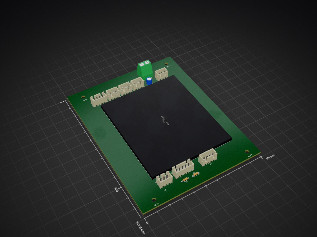
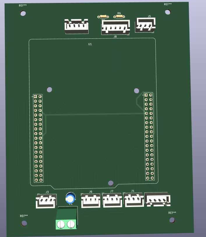
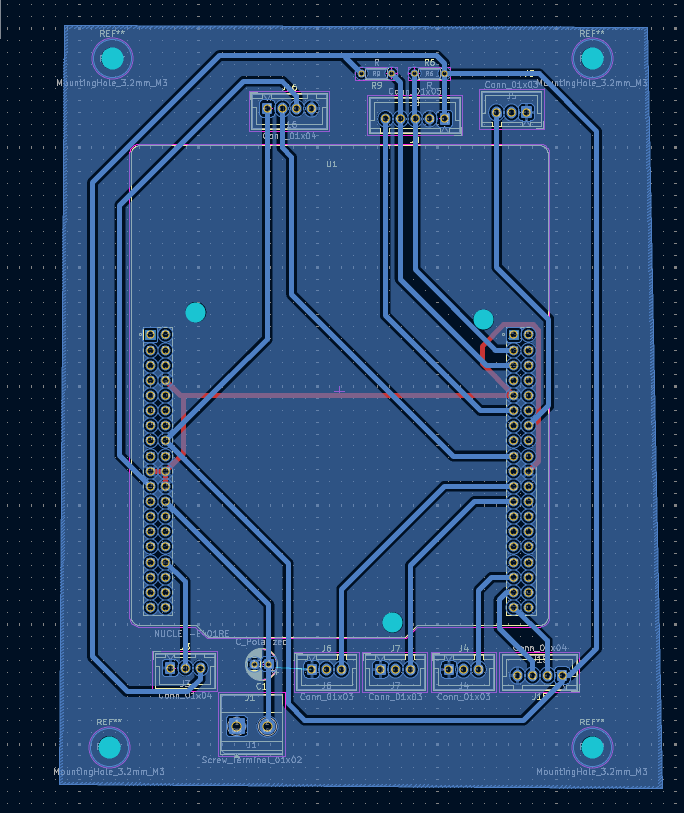
The flight controller system consists of two interconnected shield boards designed in KiCad to expand and organize the functionality of the STM32F401RE microcontroller:
1. STM32 Shield
The STM32 Shield is the main control board that interfaces with the STM32F401RE microcontroller. It houses the core power management, signal conditioning, and motor control circuitry.
3D View:
PCB Routing:
Key Features:
ESC PWM signal outputs for motor control
Power distribution and regulation
Signal conditioning for RC receiver input
UART/communication interfaces
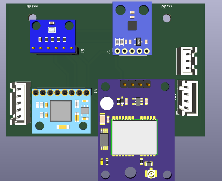
2. Sensors Shield
The Sensors Shield is a dedicated daughter board housing all the sensor modules required for flight control and navigation.
The two shields are stacked together using connector headers, providing a modular and organized hardware platform:
STM32 Shield acts as the main control and power distribution hub
Sensors Shield provides isolated sensor measurement and preprocessing
Isolated I2C and SPI buses minimize interference
Common power and ground distribution between boards
Architecture Overview (Original)
The flight controller at the top level uses the Drone class as the central aggregator that coordinates three primary functional domains: command input through the RCReceiver hierarchy, flight control through the FlightController class, and telemetry logging through the TelemetryLogger hierarchy. The RCReceiver operates as an abstract interface with concrete implementations like the IA6B class, enabling seamless integration of different receiver protocols and providing normalized command channels for throttle, roll, pitch, yaw, and flight mode selection. The TelemetryLogger uses the strategy pattern with abstract and concrete implementations (OnboardLogger for SWD/STLink-based logging and SimulationLogger for PC-based testing), allowing flexible data logging across different environments without coupling the core flight logic to any specific logging mechanism. The FlightController represents the brain of the system, aggregating four critical subsystems: the ControlSystem hierarchy (with PIDController as the concrete implementation) that processes sensor data and RC commands to generate stabilization outputs; the StateEstimator (sensor fusion engine) that aggregates the IMU (MPU6050), Barometer (BMP280), Magnetometer (GY273), and Filters (Kalman-based) to compute accurate drone attitude, altitude, and heading; the MotorController that converts control outputs into PWM signals for the ESCs; and the optional GPSReceiver (NEO6M) for position-based flight modes. This architecture establishes a clean data flow: RC inputs and sensor measurements feed into the state estimator, which produces a current state estimate; the control system consumes this state estimate and RC command inputs to compute desired motor outputs via PID control; the motor controller translates these outputs to ESC commands; and telemetry components log this entire process. The extensive use of abstract classes ensures that each component can be independently tested, replaced, or extended (e.g., swapping the Kalman filter for a complementary filter), while the layered separation maintains hardware abstraction at the bottom, control algorithms in the middle, and high-level application logic at the top—all communicating through well-defined interfaces.
17 parts. The full list of its parts is on this page, with links to each part's symbol and footprint where PCBKit's library has them.
Where can I download the Flight controller KiCad files?
From the ademda/Drone_Flight_Controller repository on GitHub, at the commit this page was made from: the board is PCB_Design/flight_controller/flight_controller.kicad_pcb and its schematic PCB_Design/flight_controller/flight_controller.kicad_sch. PCBKit opens the board in the browser, with nothing to install.
Can I use the Flight controller design in my own project?
Its repository states no licence, so its author keeps all rights: ask ademda before reusing the design.
This Repo will follow me while i m impelmenting a flight controller using stm32 blue pill board. I will be using the following components: - STM32F103C8T6 (Blue Pill) - MPU6050 (Gyro and Accelerometer) - IA6S (Receiver)…
This arm is not industrial and it will not be fast, but that is not my goal. But it will hopefully be a very nice looking arm fully capable of 6dof motion, cheap enough to keep it accessable but capable enough to…