4 layers87 × 106 mm

 ADBeta/003-UART-1602
Standard 1602 LCD Controller using a CH32V003, with UART/RS232 Receiver
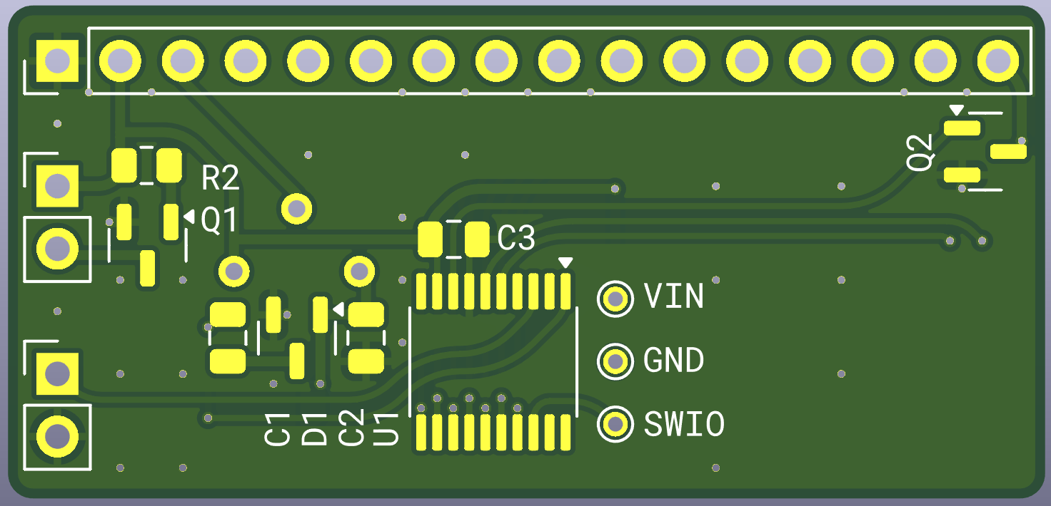
003-UART-1602 is an open-source printed circuit board by ADBeta, from the ADBeta/003-UART-1602 repository on GitHub, published under the MIT licence. It is a 2-layer board of 42 × 20 mm with 17 parts on 30 nets, routed with 74 tracks and 16 vias.
It is built around the AO3400A, AO3401A and BAT54S. Its parts include 3 capacitors, 2 resistors, 2 transistors, 1 IC and 1 diode. It belongs with the interfaces and adapters and lEDs and displays boards and the RISC-V boards of this library.

UART/RS232 Enabled controller for a basic 1602 Monochrome LCD, in 4-bit mode
using the CH32V003 - TSSOP-20 MCU
Features:
The display will read any incoming UART or RS232 Data and print it to the
screen in realtime - If the edge of the screen is exceeded, the display will
drop incoming data.
When Line Feed is received, and the Display is already on Line 2, the display
will Scroll Down, so the line being printed to remains as Line 2
See Control Characters for a list of control commands that can be used for the display
When the Display is powered on, and before it receives any UART data, the device is in the following state:
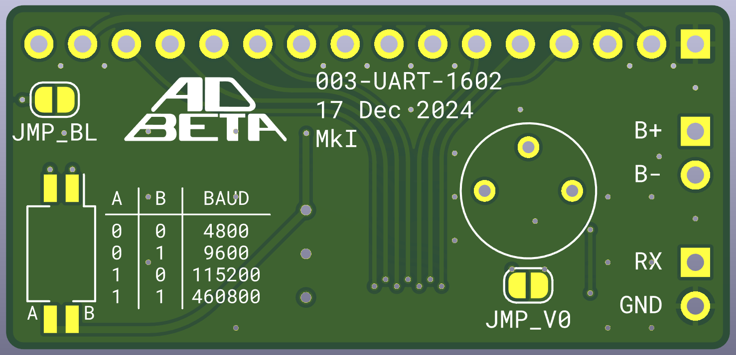
Receiver Baudrate is selected via the DIP-Switches onboard.
The setting is checked once a second so the setting can be
changed on the fly.
B1 B0  Baud
0  0   4800
0  1   9600
1  0   115200
1 1 460800There is a negative charge pump onboard that provides a near-rail negative
voltage, that is fed to one end of the contrast selection Potentiometer.
These LCDs are only officially rated at 5v, so use lower voltages
AT YOUR OWN RISK.
To disable the charge pump, do not populate the components, and short
the JMP_V0 Jumper.
The Minimum Voltage for the unit is 2.7v
BELL 0x07 - Flashes the Backlight quickly for 3 Seconds
LF 0x0A - Feeds line down, keeping Column Position
CR 0x0D - Returns to the First Column on the current line
DC1 0x11 - Device Control 1, Turns Backlight On
DC2 0x12 - Device Control 2, Turns Backlight Off
DC3 0x13 -
DC4 0x14 -
ESCAPE 0x1B - Clears the Screen and returns to position 0,0
Any Control Characters not mentioned above will be ignored.
PA1  Baud Select 1
PA2  Baud Select 2

PC0  ---
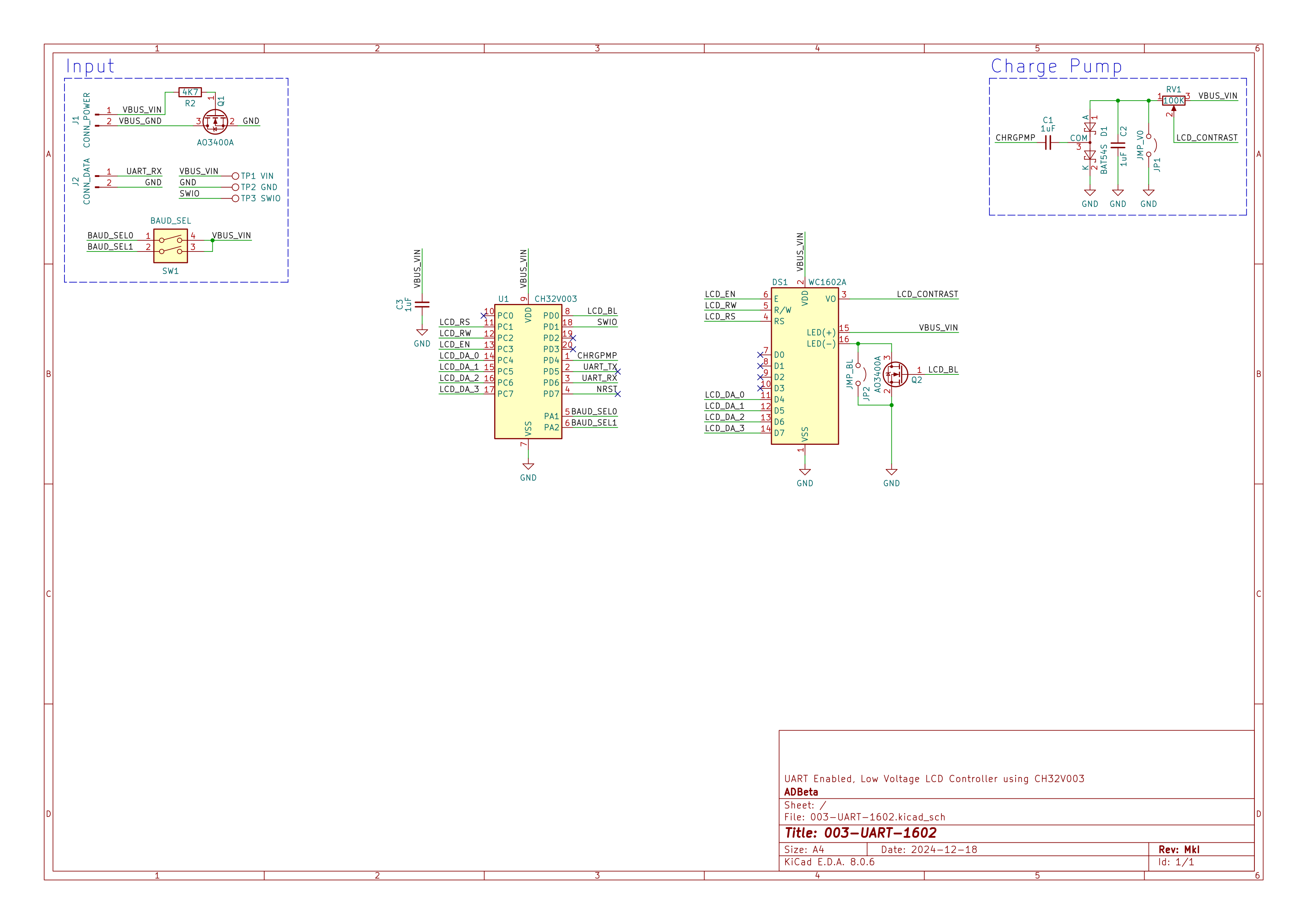
PC1  LCD_RS  Register Select
PC2  LCD_RW  Read/Write
PC3  LCD_EN  Enable
PC4  LCD_D4  Display Data Pin 4
PC5  LCD_D5  Display Data Pin 5
PC6  LCD_D6  Display Data Pin 6
PC7  LCD_D7  Display Data Pin 7

PD0  Backlight Control
PD1  !!Reserved for SWIO!!
PD2  --
PD3  --
PD4  Charge Pump PWM
PD5  TX  UART Transmit (Not Connected)
PD6  RX  UART Receive
PD7 Reserved for NRSTC1 0603 1uF 10V
C2 0603 1uF 10V
C3 0603 1uF 10V
R1 0603 4K7
R2 100K 5mm x 5mm Potentiometer
D1 BAT54S
Q1 AO3401 P-Ch
Q2 A03400 N-Ch
U1 CH32V003
SW1 1.27mm 2P DIP SwitchADBeta (c) 2024 - 2025
| Qty | Value | Footprint | References |
|---|---|---|---|
| 3 | 1uF | Capacitor_SMD:C_0805_2012Metric | C1, C2, C3 |
| 1 | 100K | Potentiometer_THT:Potentiometer_Piher_PT-6-V_Vertical | R2 |
| 1 | 4K7 | Resistor_SMD:R_0805_2012Metric | R1 |
| 1 | AO3400A | Package_TO_SOT_SMD:SOT-23 | Q2 |
| 1 | AO3401A | Package_TO_SOT_SMD:SOT-23 | Q1 |
| 1 | BAT54S | Package_TO_SOT_SMD:SOT-23 | D1 |
| 1 | BAUD_SEL | Button_Switch_SMD:SW_DIP_SPSTx02_Slide_Copal_CHS-02B_W7.62mm_P1.27mm | SW1 |
| 1 | CH32V003 | Package_SO:TSSOP-20_4.4x6.5mm_P0.65mm | U1 |
| 1 | CONN_INPUT | Connector_PinHeader_2.54mm:PinHeader_1x04_P2.54mm_Vertical | J1 |
| 1 | GND | TestPoint:TestPoint_Pad_D1.0mm | TP2 |
| 1 | JMP_BL | Jumper:SolderJumper-2_P1.3mm_Open_RoundedPad1.0x1.5mm | JP2 |
| 1 | JMP_V0 | Jumper:SolderJumper-2_P1.3mm_Open_RoundedPad1.0x1.5mm | JP1 |
| 1 | SWIO | TestPoint:TestPoint_Pad_D1.0mm | TP3 |
| 1 | VIN | TestPoint:TestPoint_Pad_D1.0mm | TP1 |
| 1 | WC1602A | Connector_PinHeader_2.54mm:PinHeader_1x16_P2.54mm_Vertical | DS1 |
It measures 42 × 20 mm and has 2 copper layers, 1.6 mm thick.
17 parts, built around the AO3400A, AO3401A and BAT54S. The full list of its parts is on this page, with links to each part's symbol and footprint where PCBKit's library has them.
From the ADBeta/003-UART-1602 repository on GitHub, at the commit this page was made from: the board is PCB/003-UART-1602.kicad_pcb and its schematic PCB/003-UART-1602.kicad_sch. PCBKit opens the board in the browser, with nothing to install.
Its repository publishes it under the MIT licence: you may reuse it on that licence's terms (keep the author's notice, and for a copyleft licence share your changes alike).


AleksaHeler/FlexNode
FlexNode is a DIY "smart home" system with a single hub and multiple flexible and customizable nodes

D0kRay/hpe-mini
Clean Hellen One starter structure for a custom rusEFI-compatible PCB.

miekush/fluke-87v-alarm-clock
ATMEGA328P based Alarm Clock PCB for the Fluke 87V


gallicchio/AMOD-and-RFMOD
The tutorial's 2x12 adapter (/mudd/133electronics/icepi-zero-dac-adc/adapterboard/) with a 2 x 6 right-angle Pmod socket on a 15 mm extension of its right-hand end, so an Icepi Zero can drive AMOD-A's and RF-MOD's Pmod…

Tjeerdie/SPECTRE
Speeduino compatible engine control unit (ECU) based around black STM32F407VET6 board.