

4 layers60 × 33.3 mm

 adamjvr/S1G-Mod7
A Sub 1GHZ Wireless Module for various Sub 1GHZ projects and applications
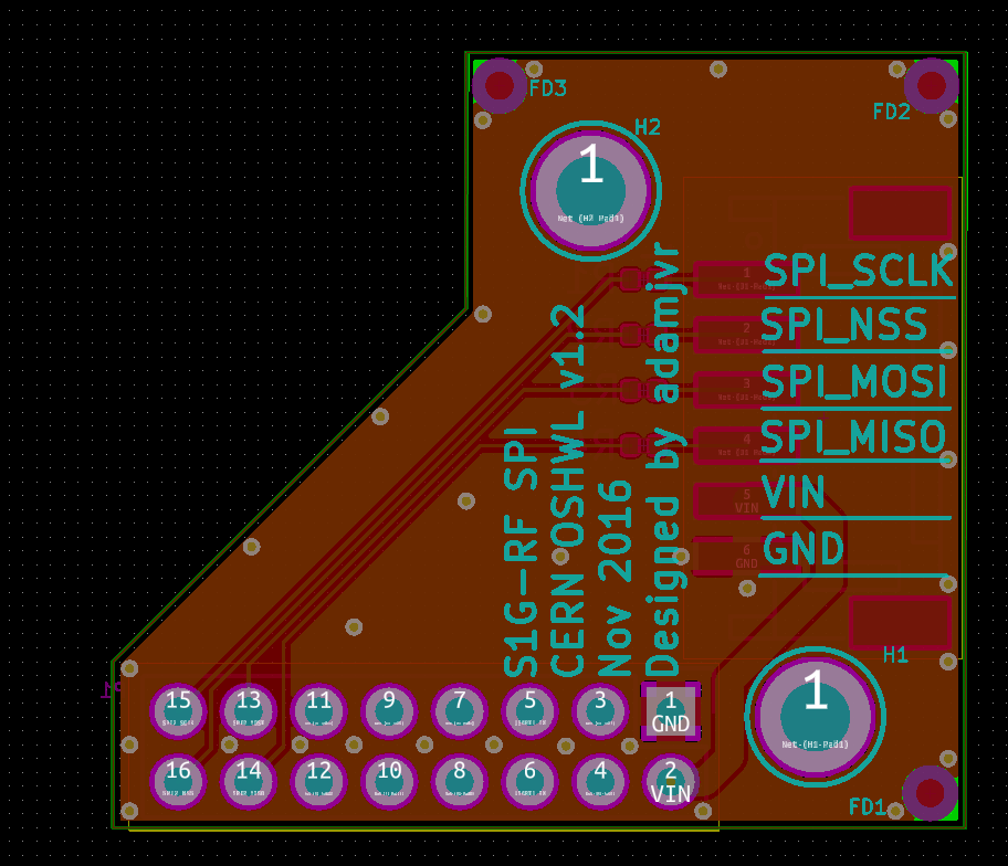
JST Adapter is an open-source printed circuit board by adamjvr, from the adamjvr/S1G-Mod repository on GitHub. It is a 2-layer board of 30.8 × 28 mm with 11 parts on 25 nets, routed with 81 tracks and 32 vias.
It is built around the TNPW0402100RBEED and S6B-PH-SM4-TB(LF)(SN). Its parts include 4 resistors and 2 connectors. It belongs with the interfaces and adapters boards of this library.
A Sub 1GHZ Wireless Module for various Sub 1GHZ projects and applications Hardware Specs
Firmware and development at: https://github.com/adamjvr/S1G-RF-firmwware
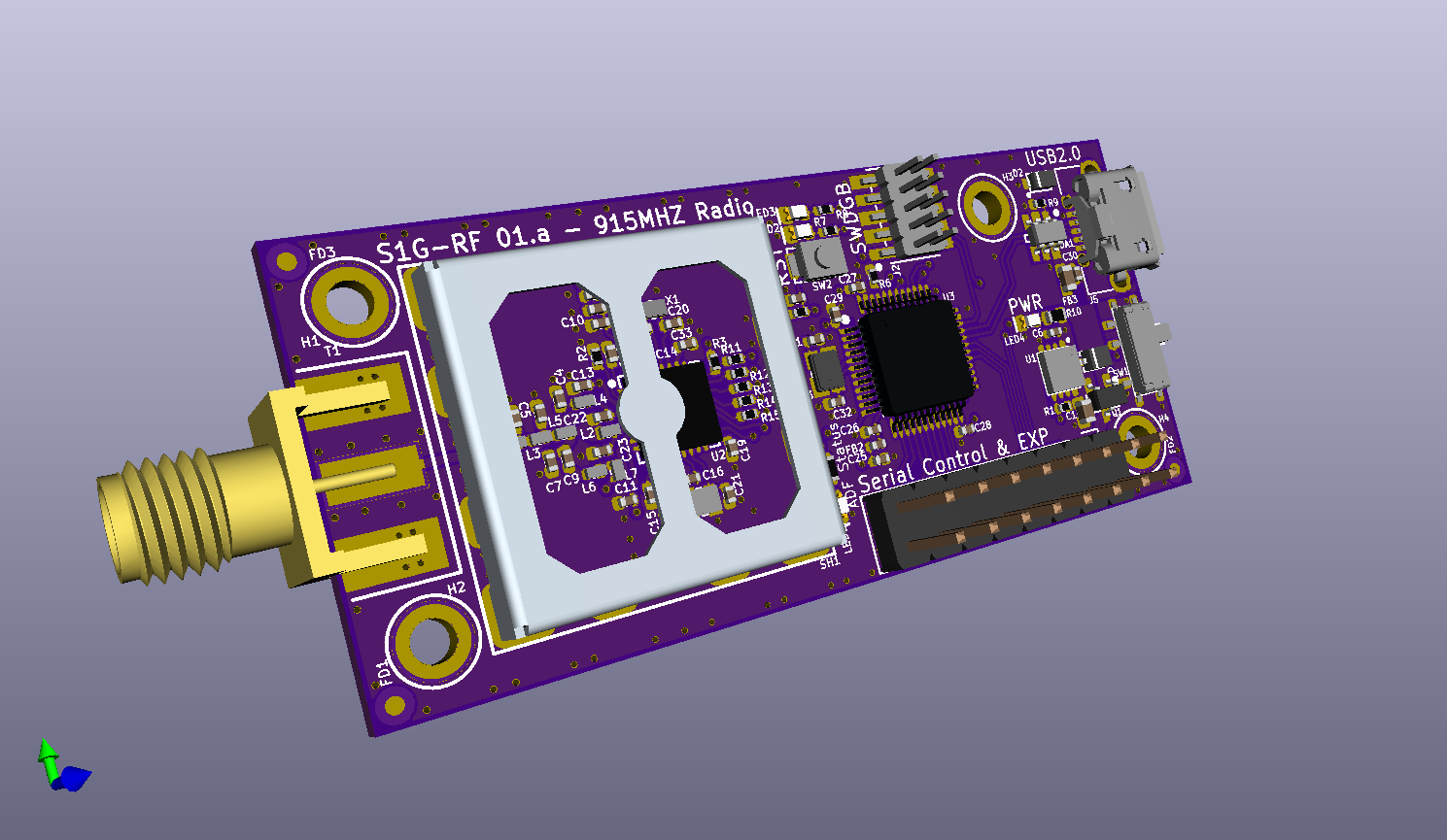
Combined RX/TX S1G-RF Module:
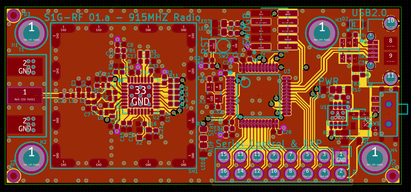 KiCAD 3D OpenGL
Separate RX/TX S1G-RF Module:
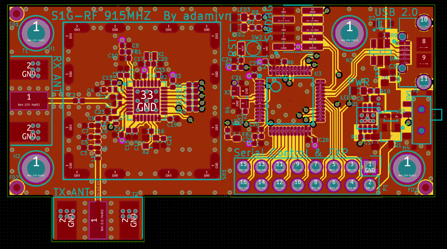 KiCAD 3D OpenGL
Adapters:
USART JST Adapter
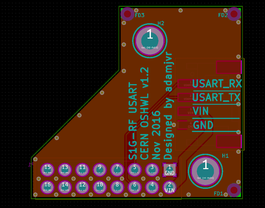 SPI JST Adapter
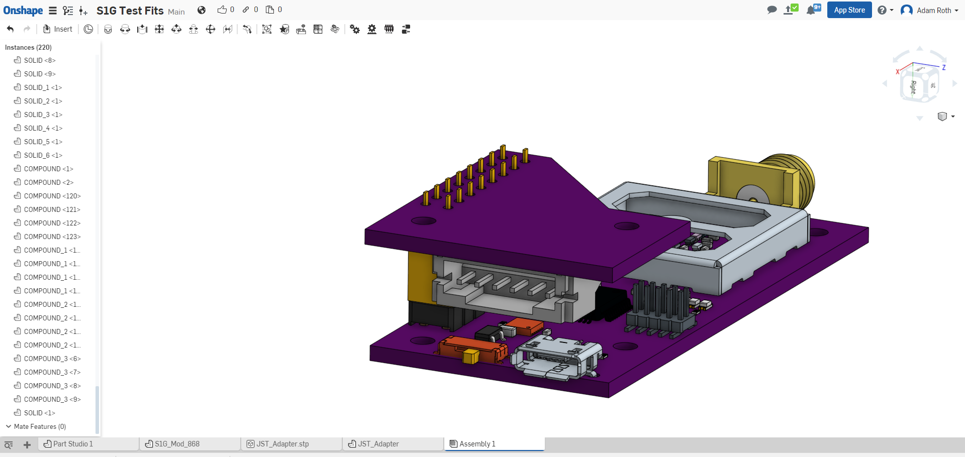
Adapter Test Fit:
| Qty | Value | Footprint | References |
|---|---|---|---|
| 4 | TNPW0402100RBEED | PCB_Footprints:R0402 | R1, R2, R3, R4 |
| 3 | FIDUCIAL | PCB_Footprints:FIDUCIAL | FD1, FD2, FD3 |
| 2 | M2.5_Hole | PCB_Footprints:M2.5_HOLE | H1, H2 |
| 1 | CONN_02X08 | Socket_Strips:Socket_Strip_Straight_2x08 | P1 |
| 1 | S6B-PH-SM4-TB(LF)(SN) | PCB_Footprints:S6B-PH-SM4-TB(LF)(SN) | J1 |


kartben/hw-testing-rack
3D-printed, tilted test shelf for 16 dev boards: sliding drawers, per-bay ESP32-S3 running Zephyr (USB/IP, power switching, metering), KiCad PCBs, OpenSCAD parts, BOM and an interactive 3D viewer

google/mozc-devices
Circuit diagrams and firmware source code for Gboard DIY keyboards


FrameworkComputer/ExpansionCards
Reference designs and documentation to create Expansion Cards for the Framework Laptop

hoglet67/RGBtoHDMI
Bare-metal Raspberry Pi project that provides pixel-perfect sampling of Retro Computer RGB/YUV video and conversion to HDMI

hackclub/OnBoard
💡 Join 1,000 teenagers and make your first PCB with a $100 grant!
It measures 30.8 × 28 mm and has 2 copper layers, 1.6 mm thick.
11 parts, built around the TNPW0402100RBEED and S6B-PH-SM4-TB(LF)(SN). The full list of its parts is on this page, with links to each part's symbol and footprint where PCBKit's library has them.
From the adamjvr/S1G-Mod repository on GitHub, at the commit this page was made from: the board is Adapters/JST/PCB/JST_Adapter.kicad_pcb. PCBKit opens the board in the browser, with nothing to install.
Its repository states no licence, so its author keeps all rights: ask adamjvr before reusing the design.