Skip to the content
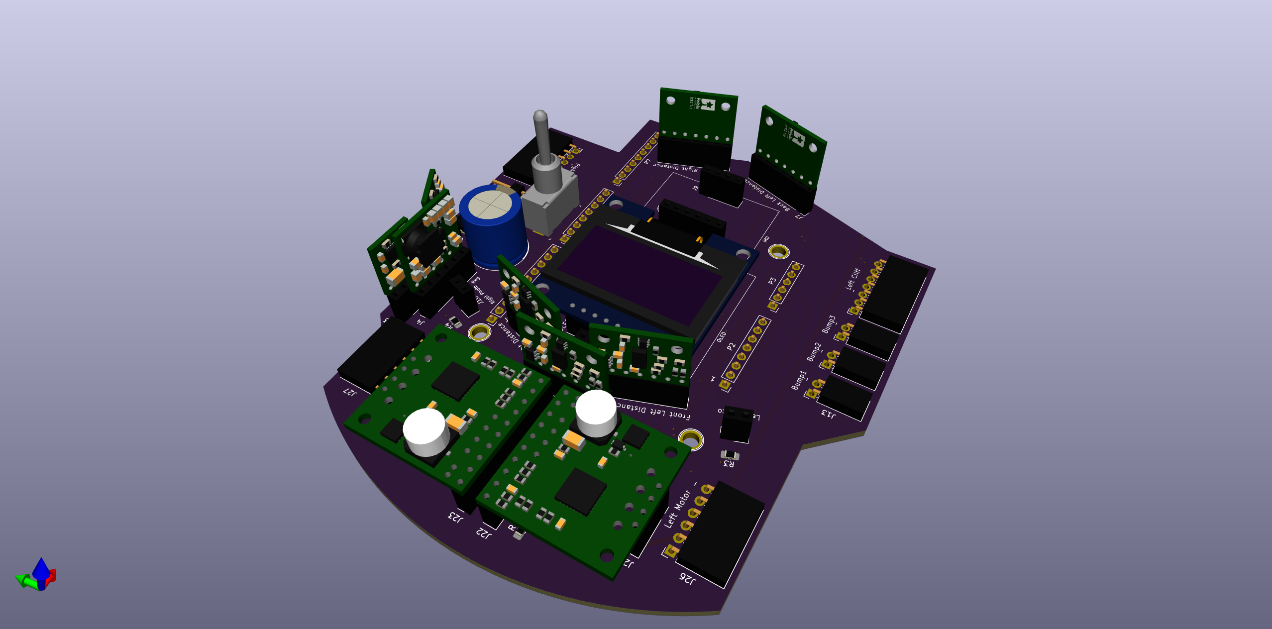
4 layers117.7 × 100.9 mmShield, the printed circuit board in 3D

A Work In Progress: My modern interpretation of the Rug Warrior Pro

Size
117.7 × 100.9 mm
Copper layers
4
Thickness
1.77 mm
Parts
46
Nets
92
Pads
240
Tracks, vias
547, 73
Pours
3
Routed
Yes
KiCad
KiCad 6 (file 20211014)
Created
5 Mar 2022
Updated
29 Sep 2022

Overview

Shield is an open-source printed circuit board by adamgreen, from the adamgreen/rugrover repository on GitHub. It is a 4-layer board of 117.7 × 100.9 mm with 46 parts on 92 nets, routed with 547 tracks and 73 vias.

It is built around the MCP23018-E/SP and 100SP1T1B4M2QE. Its parts include 35 connectors, 6 resistors, 2 capacitors, 1 IC and 1 diode. It belongs with the robots and motor control boards of this library.

Main components

2

README

README.md

Rug Rover

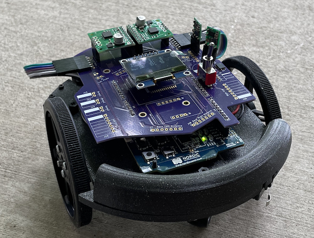
RugRover Photo of Work In Progress

Project on Hold

I am putting this project on hold for a few months while I switch back to my Robomagellan robot project in hopes of the SRS Robothon competition being run in 2023. I will take lessons learned this year while working on my RugRover and apply them to my Robomagellan bot, Ferdinand20.

Project Overview

My copy of Mobile Robotics

When I first started pursuing robotics as a hobby back in the late 1990s, one of the first books I read was "Mobile Robots: Inspiration to Implementation" by Joseph L. Jones and Anita M. Flynn. I just read it again recently and the core lessons covered by the book are just as useful today as they were back at that time even though some of the technology discussed is now a bit out of date. The mechanical, electrical, motor physics, and behavior based programming topics covered are all still relevant. The Motorola 68HC11 microcontroller and Interactive C programming language are examples of some of the more dated topics.

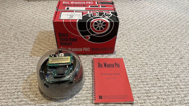
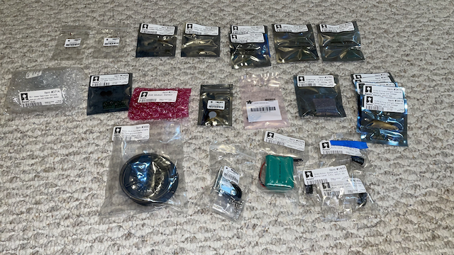
After reading the book for the first time, I ordered one of the Rug Warrior Pro kits and assembled it. I enjoyed putting it together but never did a lot of experimentation with it as I never really got one of the wheel encoders to work properly. It seemed to pick up noise from the motor as erroneous encoder tick counts.

My original Rug Warrior Pro

Having recently reread the book, I thought it would be fun to build a comparable robot using more recent technology. This Rug Rover project is my attempt to build such a robot. It features will include:

  • Similar sensors/actuators:
    • Motors with encoders
    • IR proximity sensors
    • Bumper switches
    • Microphone
    • Speaker
    • Pyroelectric sensor
    • Photo Cell light level detectors
    • LCD
  • Add in IR based downward facing cliff detectors so that I can run the robot in my loft and hopefully write software that stops it from trying to make a run down the stairs.
  • More modern nRF52 BLE capable microcontroller:
    • Exploit the BLE capabilities of this microcontroller to enable wireless debugging and programming.
    • Program in C/C++ using GCC.
    • Debug code using GDB.
  • Mechanical components will be designed in CAD and 3D printed.
  • Use KiCAD to design a custom PCB for this bot. The first iteration of the PCB will be a shield for a nRF52 development kit that I already own. Later I can design a new PCB that uses a small nRF52 module, like those offered by Adafruit.

Reading List

In addition to reading "Mobile Robots: Inspiration to Implementation" by Joseph L. Jones and Anita M. Flynn I have also read a few other books to learn more about robot design, building, and programming while working on this project:

Navigating Mobile Robots: Systems and Techniques Kalman Filter for Beginners with MATLAB Examples

Note: A free PDF version of the Navigating Mobile Robots book by Borenstein et al shown above is also available here.

Bill of Materials

Parts

Notes: I didn't end up with enough spare pins on version 1 of the PCB to connect the microphone and I2S audio components. I will experiment with these devices off of the robot for now and then add them on the next revision of the board.

Mechanical Design

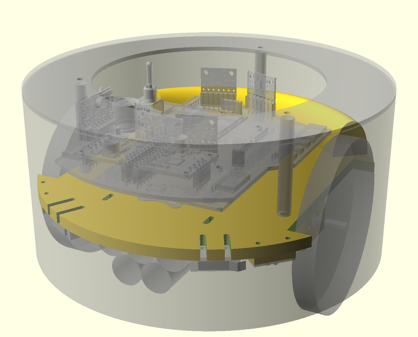
When it comes to robot building, the mechanical portions are my weakest area. On some other robot projects I have started with software drivers and then never got around to even starting on the mechanical portions since I wasn't really looking forward to it. Best to get it out of the way first on this project. Doing it first also means that I have something physical to look at and hold earlier in the project to help keep me motivated.

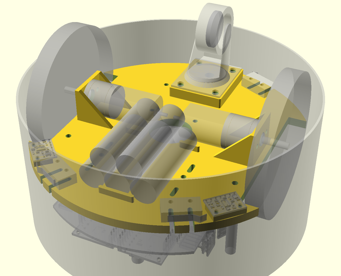
Chassis Bottom

Mechanical Highlights:

  • 3D print the mechanical parts for this robot in PETG.
  • Use OpenSCAD for the 3D design.
  • The following parts will be mounted to the underside of the robot chassis:
    • 2 x Motors
    • 1 x Caster
    • 2 x Cliff Detection Sensors (VL6180X) mounted in front of the wheels.
    • 3 x Micro Switches to detect bumper collisions.
    • 1 x 5 cell (6V) NiMH rechargeable battery.
  • Chassis has holes for attachment of following parts to the topside of the chassis:
    • 5 x Standoffs for Nordic nRF52-DK Development Kit PCB to which shield with remaining sensors/actuators will be mounted.
    • 3 x Flexible Rubber Tube Standoffs to which the bumper skirt is attached, allowing bumper to move and press against micro switches when an obstacle is encountered.
    • A separate curved cylindrical 3D printed holder that goes on the back of the robot to hold ~100g of tungsten counter weight. This moves the center of mass closer to the caster so that the robot doesn't nose dive during quick decelerations. Only having room for the batteries at the front of the bot increased the need for this counterweight.
  • A separate bumper skirt is printed to enclose the robot.
    • It is mounted to the chassis on flexible rubber tube standoffs like the Rug Warrior Pro.

Chassis Top

Lessons Learned:

  • The caster I used on this robot is probably too large for the size of the robot. Its size makes it difficult to concentrate the mass over the caster by placing heavy things like the batteries near it on the bottom. I now see why the original RugWarrior Pro used the smaller non-swiveling ball caster. It took up less space and allowed the battery pack to be placed between the axle and the caster.
  • Tungsten putty is actually a soft moving liquid. The putty I placed in the cylindrical 3D printed holder at the back of the robot leaked out over time and some of it flowed out into the rear micro switch. I was able to take the robot apart and clean up the leaked putty. I designed and printed a bottom for the holder that I welded in place with a soldering iron to contain the tungsten putty inside.

Electronics Design

Once I had the mechanical design mostly figured out, I moved onto the design of the electronics in KiCad.

Electronic Highlights:

  • The initial version of the electronics will use the Nordic nRF52 DK as its base and the custom robot electronics will be added as a custom shield.
  • The shield design is 4-layer to make it easier to route the signals all around the board without worrying about ground and power. The layout is a bit complicated as the Arduino header format used by the nRF52 DK has most of the signals on one side of the board but I want to place input/output connectors on both sides of the board.
  • Most of the sensors and actuators are connected to the PCB via 0.1" headers.
  • Version 1 of the shield includes:
    • Dual TB9051FTG motor controllers
    • Quadrature motor encoders
    • Dual photo cells
    • PIR motion sensor
    • Three switches for bumper skirt obstacle detection
    • SPI based OLED screen
    • One I2C bus for connection to:
      • 5 x VL53L1X ToF Obstacle Detection Sensors (3 front facing & 2 back facing).
      • 2 x VL6180X ToF Cliff Detection Sensors mounted in front of the wheels.
      • 1 x Adafruit Precision NXP 9-DOF IMU
      • 1 x 16 channel MCP23018 I/O port expander used for:
        • Asserting VL53L1X and VL6180X XSHUT pins to init each one separately and give them unique I2C addresses.
        • Reading of the multiple VL53L1X and VL6180X GPIO pins.
  • Multiple voltage supplies:
    • 6V Directly from Batteries for Motors
    • 5V from Buck Regulator for TB9051FTG Motor Controllers
    • 12V from Boost Regulator for PIR Sensor
    • 3.3V from Buck Regulator for rest of Electronics

3D Board View
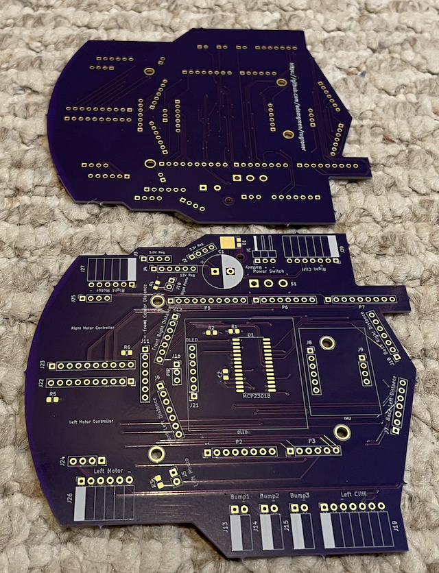
Photo of boards back from OSHPark

Schematic PDF

Software

Once the mechanical and electronics were far enough along I could start writing the software. This should be where I spend the most amount of time. I will provide links to notes about each software component as I write its code.

Software Components:

  • mriblue Debug Monitor: A FLASH resident bootloader and debug monitor that runs on the nRF52832 to enable wireless debugging and programming over Bluetooth Low Energy (BLE) from GDB.
  • SH1106 SPI based OLED Driver:
    • An Adafruit GFX based display driver.
    • The drawing primitives just modify an in-memory version of the display's frame buffer.
    • A separate refresh() method is used to copy that frame buffer to the SH1106 OLED driver.
    • The refresh() copy makes use of the nRF52's SPI Master peripheral's EasyDMA functionality to perform most of this SPI transfer in the background with little CPU intervention. The CPU is just used to setup the transfer for each of the 8 frame buffer pages.
  • QuadratureDecoderHardware: This driver uses the QDEC peripheral on the nRF52832 to count quadrature encoder ticks. It requires almost no CPU cycles but there is only 1 instance on the microcontroller so I use it for the left encoder only.
  • QuadratureDecoderSoftware: This driver uses the GPIOTE to fire an ISR on each edge of both the A and B signals from a quadrature encoder. The ISR uses the previous and current encoder signal states to determine if the count should be incremented or decremented. A maximum of 4 encoders can make use of this library if nothing else is making use of the nRF52's 8 GPIOTE channels. The driver needs 2 GPIOTE channels for each encoder, 1 per encoder signal.
  • SAADCScanner: This driver runs in the background, reading the specified analog channels (up to 8 on the nRF52832) in a loop using the nRF52's SAADC peripheral:
    • At the end of each loop, an ISR is triggered to process the most current readings. This allows for minimal CPU overhead.
    • It can be configured for manual scanning rather than continuously scanning in the background. I am currently using it this way since it would run at 50kHz in auto mode and the ISR kept showing up in call stacks when I profiled the code.
    • The application can read out a channel's value at a rate slower than the ISR firing rate. The returned structure contains the minimum, maximum, and mean values seen since the last read.
    • The application can also specify trigger limits for the minimum and/or maximum analog values to be expected. Readings outside of these limits will be tracked in the returned structure and can also trigger a callback to a caller provided ISAADCScannerNotification interface.
    • This driver is currently only used to monitor the motor currents for each wheel. In the future it can be used to monitor the light levels detected by the 2 photocells.
  • DualTB9051FTGDrivers: This driver allows for the control of 2 Toshiba TB9051FTG H-bridge chips, one for each motor on the robot. It uses 4 channels of the nRF52's PWM peripheral to control the torque and speed of the motors with minimal CPU intervention.
  • GlobalTimer: Uses TIMER2 to implement an Arduino like micros() API to return a 32-bit value indicating the number of microseconds since reset.
  • PID: Header only class that implements a PID (proportional, integral, derivative) algorithm. It is inspired by Brett Beauregard's Arduino PID Library and the PID e-book available on controlguru.
  • DifferentialDrive: This driver implements closed loop control of RugRover's differential drive. It is built on top of the DualTB9051FTGDrivers and Quadrature Decoder libraries. It also has a getStats() method which exposes internal state of the motors, encoders, and PID algorithm to the user:
    • The requested velocity and the actual measured velocity of each wheel.
    • The running total of encoder ticks for each wheel.
    • The motor power (-100% to 100%) being used for each wheel.
    • The most recent motor current measurement (mA) taken for each wheel.
    • The maximum motor current measurement (mA) taken for each wheel so far.
    • Whether any motor faults or over-current events have been detected by the motor drivers.
    • The mAh consumed by the motors since reset.
    • A flag to indicate whether the PID is running in manual or auto mode.
  • Navigate: Class used to navigate between a list of user specified waypoints and track the real world location of the robot based on wheel odometry.
  • CircularBuffer: Generic lock-free circular buffer that supports multiple producers and consumers.
  • I2CAsync: This driver makes it easier to use the nRF52's TWIM peripheral asynchronously. It makes use of the CircularBuffer to allow ISRs running at different interrupt priorities to communicate with several different I2C devices.
  • AdafruitPrecision9DoF: This driver uses the I2CAsync driver to communicate with the FXOS8700CQ accelerometers/magnetometers and the FXAS21002C gyros.
    • The desired refresh rate (100Hz, 200Hz, or 400Hz) is specified in the constructor.
    • The FXOS8700CQ will pull a pin low when the next sample is ready at the specified rate.
    • This falling edge generates an interrupt that causes the next I2C reads of the accelerometers, magnetometers, and gyros to be queued up in the I2CAsync queue.
    • The getRawSensorValues() method, typically called from the main thread, will block until all of the queued up reads are completed.
  • OrientationKalmanFilter: Implements a Kalman filter which takes the raw accelerometer, magnetometer, and gyro measurements from the AdafruitPrecision9DoF object and generates a 3D orientation quaternion.
    • It also contains a method which can extract the compass heading from this 3D orientation as well.
    • The code for this filter was based on what I learned from reading "Kalman Filter for Beginners with MATLAB Examples" by Phil Kim. The system model used in this filter came from Chapter 13 of this book.
    • I documented many of the required calibration steps earlier while working on my Ferdinand14 project.
    • The processing/calibration folder contains a port of the calibration program which will work with this robot. The robot does need to be running the "Test IMU Raw" option from the debug menu to send the required measurements to this calibration program.
    • The processing/orientation folder contains a program that visualizes the 3D orientation of the robot in real time. The robot needs to be running the "Test IMU Orientation" option from the debug menu in order to send the required quaternion data over BLE to this program.
    • Both of the processing programs above use a TCP/IP socket to connect to the mriblue program on port 3334. This gives it access to extra data sent from the robot over BLE that isn't meant for GDB.
  • HeadingKalmanFilter: Implements a Kalman filter which fuses Z axis gyro angular rate measurements with angle heading change measurements calculated from wheel odometry.
    • The code for this filter was also based on what I learned from reading "Kalman Filter for Beginners with MATLAB Examples" by Phil Kim.
    • The system model used by this filter was one I created on my own. It tracks:
      • The current heading angle in radians.
      • The current gyro angular turn rate in radians/sec.
      • The estimate of the gyro drift in radians/sec. Having an estimate of this value allows for the filter to obtain a more accurate turn rate from the gyro than possible otherwise.
    • I determined the first two variance values to place in the Q matrix by setting the DEBUG_CALCULATE_STATS_FOR_SYSTEM_MODEL macro to true in main.cpp so that it would dump stats about how much this model tended to deviate from the real world while just using wheel odometry. I then set the variance for the drift parameter to 0.0 since the model maintains it as a constant and in the real world it should vary slowly over time.
    • The GYRO_ERROR was calculated and dumped by the orientation.pde utility while I was calibrating the IMU for the OrientationKalmanFilter.
    • I estimate that the ODOMETRY_ERROR error is typically the result of a +/- 1 encoder tick's influence on the wheel odometry calculation of the heading angle delta.

Parts

46
QtyValueFootprintReferences
410kResistor_SMD:R_0805_2012Metric_Pad1.20x1.40mm_HandSolderR3, R4, R5, R6
4CONN_01X01Socket_Arduino_Mega:Arduino_1pinP8, P9, P11, P12
21kResistor_SMD:R_0805_2012Metric_Pad1.20x1.40mm_HandSolderR1, R2
10.1uFCapacitor_SMD:C_0805_2012Metric_Pad1.18x1.45mm_HandSolderC2
112V Boost RegulatorConnector_PinSocket_2.54mm:PinSocket_1x06_P2.54mm_VerticalJ4
12200uF 25VCapacitor_THT:CP_Radial_D13.0mm_P5.00mmC1
13.3V 500mA RegulatorConnector_PinSocket_2.54mm:PinSocket_1x04_P2.54mm_VerticalJ2
15.0V 500mA RegulatorConnector_PinSocket_2.54mm:PinSocket_1x04_P2.54mm_VerticalJ3
1AnalogConnector_PinHeader_2.54mm:PinHeader_1x06_P2.54mm_VerticalP3
1Back Left DistanceConnector_PinSocket_2.54mm:PinSocket_1x07_P2.54mm_VerticalJ7
1Back Right DistanceConnector_PinSocket_2.54mm:PinSocket_1x07_P2.54mm_VerticalJ18
1BatteryConnector_PinHeader_2.54mm:PinHeader_1x03_P2.54mm_HorizontalJ1
1Bump1Connector_PinSocket_2.54mm:PinSocket_1x02_P2.54mm_HorizontalJ13
1Bump2Connector_PinSocket_2.54mm:PinSocket_1x02_P2.54mm_HorizontalJ14
1Bump3Connector_PinSocket_2.54mm:PinSocket_1x02_P2.54mm_HorizontalJ15
1Front Center DistanceConnector_PinSocket_2.54mm:PinSocket_1x07_P2.54mm_VerticalJ11
1Front Left DistanceConnector_PinSocket_2.54mm:PinSocket_1x07_P2.54mm_VerticalJ6
1Front Right DistanceConnector_PinSocket_2.54mm:PinSocket_1x07_P2.54mm_VerticalJ17
1GPIOConnector_PinHeader_2.54mm:PinHeader_1x10_P2.54mm_VerticalP5
1GPIOConnector_PinHeader_2.54mm:PinHeader_1x08_P2.54mm_VerticalP6
1GPIOConnector_PinHeader_2.54mm:PinHeader_1x09_P2.54mm_VerticalP7
1IMU-1Connector_PinSocket_2.54mm:PinSocket_1x06_P2.54mm_VerticalJ8
1IMU-2Connector_PinSocket_2.54mm:PinSocket_1x04_P2.54mm_VerticalJ9
1LMotor-1Connector_PinSocket_2.54mm:PinSocket_1x10_P2.54mm_VerticalJ22
1LMotor-2Connector_PinSocket_2.54mm:PinSocket_1x04_P2.54mm_VerticalJ24
1Left CliffConnector_PinSocket_2.54mm:PinSocket_1x07_P2.54mm_HorizontalJ19
1Left MotorConnector_PinSocket_2.54mm:PinSocket_1x06_P2.54mm_HorizontalJ26
1Left PhotoConnector_PinSocket_2.54mm:PinSocket_1x02_P2.54mm_VerticalJ5
1MCP23018Package_SO:SOIC-28W_7.5x17.9mm_P1.27mmU1
1OLEDConnector_PinSocket_2.54mm:PinSocket_1x07_P2.54mm_VerticalJ21
1PIRConnector_PinSocket_2.54mm:PinSocket_1x03_P2.54mm_VerticalJ16
1PowerConnector_PinHeader_2.54mm:PinHeader_1x08_P2.54mm_VerticalP2
1Power Switchdigikey-footprints:Toggle_Switch_100SP1T1B4M2QES1
1RMotor-1Connector_PinSocket_2.54mm:PinSocket_1x10_P2.54mm_VerticalJ23
1RMotor-2Connector_PinSocket_2.54mm:PinSocket_1x04_P2.54mm_VerticalJ25
1Right CliffConnector_PinSocket_2.54mm:PinSocket_1x07_P2.54mm_HorizontalJ20
1Right MotorConnector_PinSocket_2.54mm:PinSocket_1x06_P2.54mm_HorizontalJ27
1Right Photo CellConnector_PinSocket_2.54mm:PinSocket_1x02_P2.54mm_VerticalJ10
1SS10P6-M3/86APackage_TO_SOT_SMD:TO-277AD1

Similar boards

  • 2 layers111 × 96.5 mmErgoDOX, the printed circuit board in 3D

    ErgoDOX

    regack/depot

    Stuff

    184 parts11
  • 4 layers225 × 111.5 mmInductorSchem, the printed circuit board in 3D

    InductorSchem

    arcasoy/The-Inductor

    Custom induction keyboard build

    165 parts
  • 2 layers426.4 × 498.2 mmRotonometron v1, the printed circuit board in 3D

    Rotonometron v1

    Zoestra/Rotonometron

    Split Keyboard PCB with all the bells and whistles

    294 partsGPL-3.0
  • 4 layers313 × 206 mmOverHead v1, the printed circuit board in 3D

    OverHead v1

    stefanofinetti/MF_OverHead_Panel

    Complete project for the Airbus A319/320/321/330 OverHead Panel

    416 parts5GPL-3.0
  • 2 layers59.1 × 101.4 mmFlight computer, the printed circuit board in 3D

    Flight computer

    nakujaproject/N3FlightComputer-PCB

    Electrical schematics and PCB for N3 flight computer

    48 parts1MIT
  • 2 layers715.5 × 705.5 mmFrontpanel, the printed circuit board in 3D

    Frontpanel

    Pconst167/sol-1

    Sol-1 is a homebrew CPU and Minicomputer built from 74HC logic. It is published here for educational purposes.

    299 parts1

Questions

How big is the Shield PCB?

It measures 117.7 × 100.9 mm and has 4 copper layers, 1.77 mm thick.

What parts does the Shield use?

46 parts, built around the MCP23018-E/SP and 100SP1T1B4M2QE. The full list of its parts is on this page, with links to each part's symbol and footprint where PCBKit's library has them.

Where can I download the Shield KiCad files?

From the adamgreen/rugrover repository on GitHub, at the commit this page was made from: the board is hardware/shield.kicad_pcb and its schematic hardware/Motors.kicad_sch. PCBKit opens the board in the browser, with nothing to install.

Can I use the Shield design in my own project?

Its repository states no licence, so its author keeps all rights: ask adamgreen before reusing the design.