2 layers13.5 × 12.6 mm
RP2040 SWD Adapter
adamgreen/mri-swd
Work In Progress! - MRI-SWD - GDB compatible hardware probe which allows debugging of Cortex-M based microcontrollers over SWD.
2 parts1Apache-2.0

 adamgreen/mri-swd1
Work In Progress! - MRI-SWD - GDB compatible hardware probe which allows debugging of Cortex-M based microcontrollers over SWD.
Mri swd is an open-source printed circuit board by adamgreen, from the adamgreen/mri-swd repository on GitHub, published under the Apache-2.0 licence. It is a 2-layer board of 41.7 × 68.6 mm with 8 parts on 43 nets, routed with 107 tracks and 1 via.
Its parts include 3 connectors, 2 switches, 1 resistor, 1 IC and 1 diode. It belongs with the interfaces and adapters boards and the RP2040 boards of this library.
mri-swd is a Pico W based debug probe for debugging Cortex-M based microcontrollers with the GNU debugger (GDB). GDB can connect to the mri-swd debug probe over WiFi and the debug probe then connects to the debug target using SWD.
mri-swd project.mri-swd.mri-swd but might be in the future.mri-swd firmware.mri-swd.mri-swd and connect GDB.config.h to customize the mri-swd firmware.mri-swd PCB development.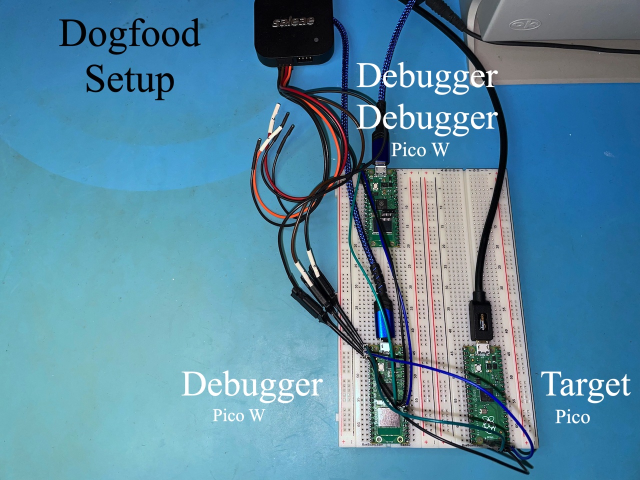
mri-swd firmware itself and other RP2040 based projects. The WiFi abilities make it really useful for debugging RP2040 based electronics on mobile robot paltforms. Dogfooding it like this continue to surface more issues that can then be addressed to make it even better. I will continue with this dogfooding for several more months yet before deciding whether I should port mri-swd to the Raspberry Pi Debug Probe and make a more public announcement about this alternative debug probe firmware.mri-swd firmware is initially being developed to run on the low cost Pico W. It will use the Pico W's WiFi capabilities to wirelessly communicate with GDB. No intermediate program like OpenOCD will be required since the mri remote debug stub functionality will be running on the Pico W itself.load (FLASH Programming of RP2040, RP2350, and nRF52xxx)step and next (Single Stepping)break (Hardware Breakpoints)watch, awatch, rwatch (Hardware Watchpoints)monitor reset [halt] (Reboot the microcontroller)monitor detach (Power down target DAP and shutdown mri-swd)info thread and thread:
Currently the SSID and Password for accessing the WiFi network need to be compiled into the firmware. You need to create a wifi_config.cmake file in the root of the project to provide the values appropriate for your network. Here is an example of its required contents (update with your particular SSID and password):
wifi_config.cmake Example
set(WIFI_SSID YourSSID)
set(WIFI_PASSWORD YourPassword)
This file is included in the repository's .gitignore so that it isn't accidentally committed and pushed to a public server.
Note: I will provide a way to set these WiFi settings over USB in the future.
This repository contains the pico-sdk and mri core repositories as submodules. The following GNU Make command will initialize these submodules:
make initGNU Make can also be used to kick off the initial build:
make allThis will generate output files in the build/ folder. Subsequent builds can be performed by executing the Makefile now found in this folder:
cd build/
makeAs this is a pico-sdk project, it uses CMake to perform the build. The above described /Makefile has only been tested on macOS but may work on other Posix systems such as Linux as well. If you are running on Windows and are already familiar with using CMake to build pico-sdk based projects on that platform then you can instead perform the setup manually:
cd mri
git submodule update --init
cd pico-sdk
git submodule update --init
mkdir build
cd build
cmake -G "NMake Makefiles" ..
nmake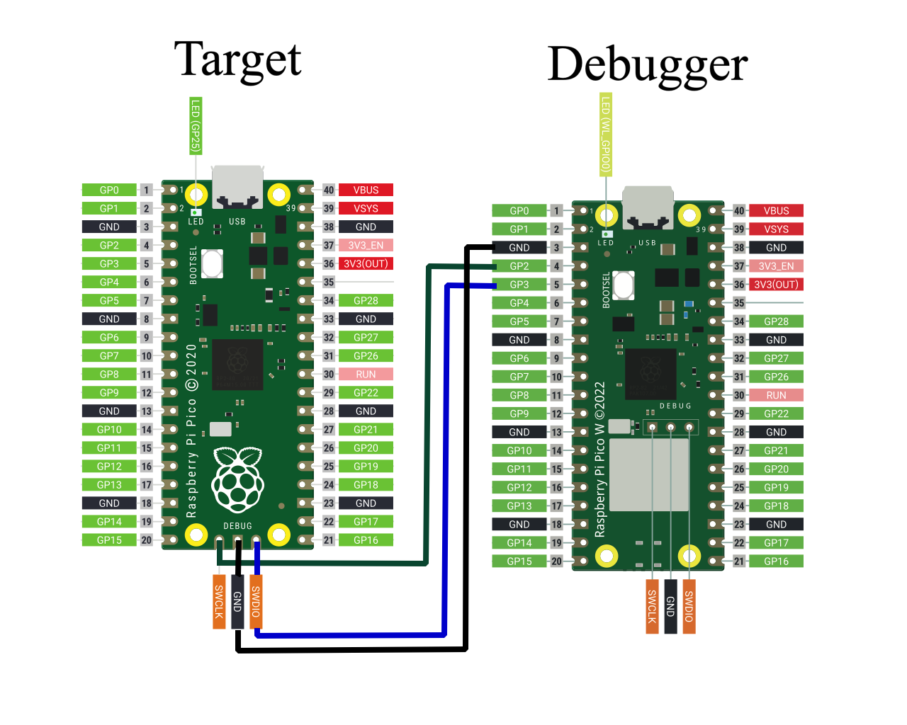
Currently only 2 signal wires (and ground) need to be connected between the target RP2040 device and the Pico W based debugger device:
| Pico W Debugger | Pico Target |
|---|---|
| GPIO 2 | SWCLK |
| GPIO 3 | SWDIO |
| Gnd | Gnd |
Both devices, target and debugger, need power. It is common to power each of the devices via their individual USB connectors.
Now that mri-swd supports using an Adafruit 128x32 Monochrome OLED for showing its status, what follows is now the preferred method of determining the IP address assigned by DHCP.
When mri-swd first powers up it will show an animating WiFi icon as it attempts to connect to the specified WiFi network:

Once the connection has been made the logo will stop animating and the DHCP assigned IP address will be shown below the logo:
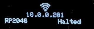
The assigned IP address is shown as 10.0.0.201
Originally the only way to determine the DHCP assigned IP address was by using the output mri-swd sends to the USB based serial port as described below.
A terminal program must be connected to the USB based serial connection made available from the Pico W running the mri-swd firmware. When mri-swd is starting up output like the following will be seen in this terminal session:
  info: main.cpp:33 main() - Starting up...
 info: mri_platform.cpp:214 attemptSwdAttach() - Found DPv2 SWD Target=0x01002927 with DPIDR=0x0BC12477
 info: mri_platform.cpp:227 attemptSwdAttach() - Initializing target's debug components...
debug: swd.cpp:645 checkAP() - peripheralComponentIDs[]=
debug: swd.cpp:646 checkAP() - {
debug: swd.cpp:649 checkAP() -     0x00000004
debug: swd.cpp:649 checkAP() -     0x00000000
debug: swd.cpp:649 checkAP() -     0x00000000
debug: swd.cpp:649 checkAP() -     0x00000000
debug: swd.cpp:649 checkAP() -     0x000000C0
debug: swd.cpp:649 checkAP() -     0x000000B4
debug: swd.cpp:649 checkAP() -     0x0000000B
debug: swd.cpp:649 checkAP() -     0x00000000
debug: swd.cpp:649 checkAP() -     0x0000000D
debug: swd.cpp:649 checkAP() -     0x00000010
debug: swd.cpp:649 checkAP() -     0x00000005
debug: swd.cpp:649 checkAP() -     0x000000B1
debug: swd.cpp:651 checkAP() - }
debug: swd.cpp:660 checkAP() - CPUID=0x410CC601
 info: mri_platform.cpp:234 attemptSwdAttach() - SWD initialization complete!
 info: mri_platform.cpp:240 initNetwork() - Initializing network...
 info: mri_platform.cpp:251 initNetwork() - Attempting to connect to Wi-Fi router...
 info: mri_platform.cpp:254 initNetwork() - Connected to Wi-Fi router.
 info: gdb_socket.cpp:36 init() - Starting server at 10.0.0.201 on port 2331
 info: mri_platform.cpp:795 initDWT() - CPU supports 2 hardware watchpoints.
 info: mri_platform.cpp:857 initFPB() - CPU supports 4 hardware breakpoints.
The third line up from the bottom shows the 10.0.0.201 IP address assigned to the mri-swd device on this particular network. Take note of this IP address so that it can be used later when attaching GDB.
The following is an example shell session where GDB is launched and told to connect and start debugging a RP2040 microcontroller via the WiFi IP address that was noted in the previous section (10.0.0.201). Port 2331 is the default TCP/IP port number used by mri-swd but it can be changed in the config.h file discussed further down in this documentation.
$ arm-none-eabi-gdb -ex "set target-charset ASCII" -ex "set print pretty on" -ex "set remotelogfile mri.log" -ex "target remote 10.0.0.201:2331" -ex "set mem inaccessible-by-default off" test.elf

GNU gdb (Arm GNU Toolchain 12.2 (Build arm-12-mpacbti.34)) 13.1.90.20230307-git
Copyright (C) 2023 Free Software Foundation, Inc.
License GPLv3+: GNU GPL version 3 or later <http://gnu.org/licenses/gpl.html>
This is free software: you are free to change and redistribute it.
There is NO WARRANTY, to the extent permitted by law.
Type "show copying" and "show warranty" for details.
This GDB was configured as "--host=aarch64-apple-darwin20.6.0 --target=arm-none-eabi".
Type "show configuration" for configuration details.
For bug reporting instructions, please see:
<https://bugs.linaro.org/>.
Find the GDB manual and other documentation resources online at:
    <http://www.gnu.org/software/gdb/documentation/>.

For help, type "help".
Type "apropos word" to search for commands related to "word"...
Reading symbols from build/QuadratureDecoder.elf...
Remote debugging using 10.0.0.201:2331
get_absolute_time () at /depots/QuadratureDecoder/pico-sdk/src/common/pico_time/include/pico/time.h:63
63	    update_us_since_boot(&t, time_us_64());
(gdb) load
Loading section .boot2, size 0x100 lma 0x10000000
Loading section .text, size 0x7130 lma 0x10000100The target's UART pins can be connected to the mri-swd debugger as shown in this table:
| Pico W Debugger | Pico Target |
|---|---|
| GPIO 0 | UART Rx |
| GPIO 1 | UART Tx |
| Gnd | Gnd |
If those connections are made then the target can configure its UART for 230400-8-N-1 communication and this UART will then be accessible from the PC host connected to mri-swd on TCP/IP port 2332 (can be changed in config.h). The PC host can then use a simple TCP/IP terminal emulator such as telnet to communicate with the target's UART over WiFi on this port:
~$ telnet -N 10.0.0.201 2332
Trying 10.0.0.201...
Connected to 10.0.0.201.
Escape character is '^]'.
Send this data to target over UART and have it loop it back to the PC!
Send this data to target over UART and have it loop it back to the PC!
^]
telnet> quit
Connection closed.
Note: The IP address to be used with telnet above should match the IP address you use for connecting GDB to the same mri-swd debug probe.
The root folder contains a config.h file which can be used to customize the mri-swd firmware. This header file allows configuration of things such as:
mri-swd firmware:
logError() calls let the user know about unexpected errors. They can be disabled per module in config.h but typically should be left enabled.logDebug() calls give information about the inner workings of the code and are most useful to mri-swd developers. They can be disabled per module in the config.h header.logInfo() calls inform the user what the debugger firmware is currently doing. They can't be disabled.mri-swd and GDB.mri-swd is first attempting to connect to the specified WiFi network, it will show the following WiFi logo animation:10.0.0.201 can be seen along with 2 additional status messages on the bottom line:
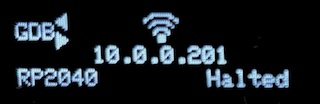
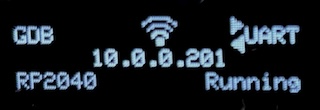
RP2040.Halted.mri-swd's port 2331, the word GDB will show up in the upper left hand corner of the display. Similarly when a terminal program like Telnet connects to mri-swd's port 2332, the word UART will show up in the upper right hand corner. The following image shows clients connected to both ports. It also shows the current state of the target as Running in the lower right hand corner: 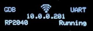
GDB and UART designators when data is being sent to and from each of their corresponding TCP/IP clients:
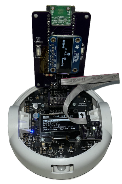
I have designed a PCB that allows attaching a PicoW to my Pololu 3π+ 2040 robot. The images below show my current progress on that project.
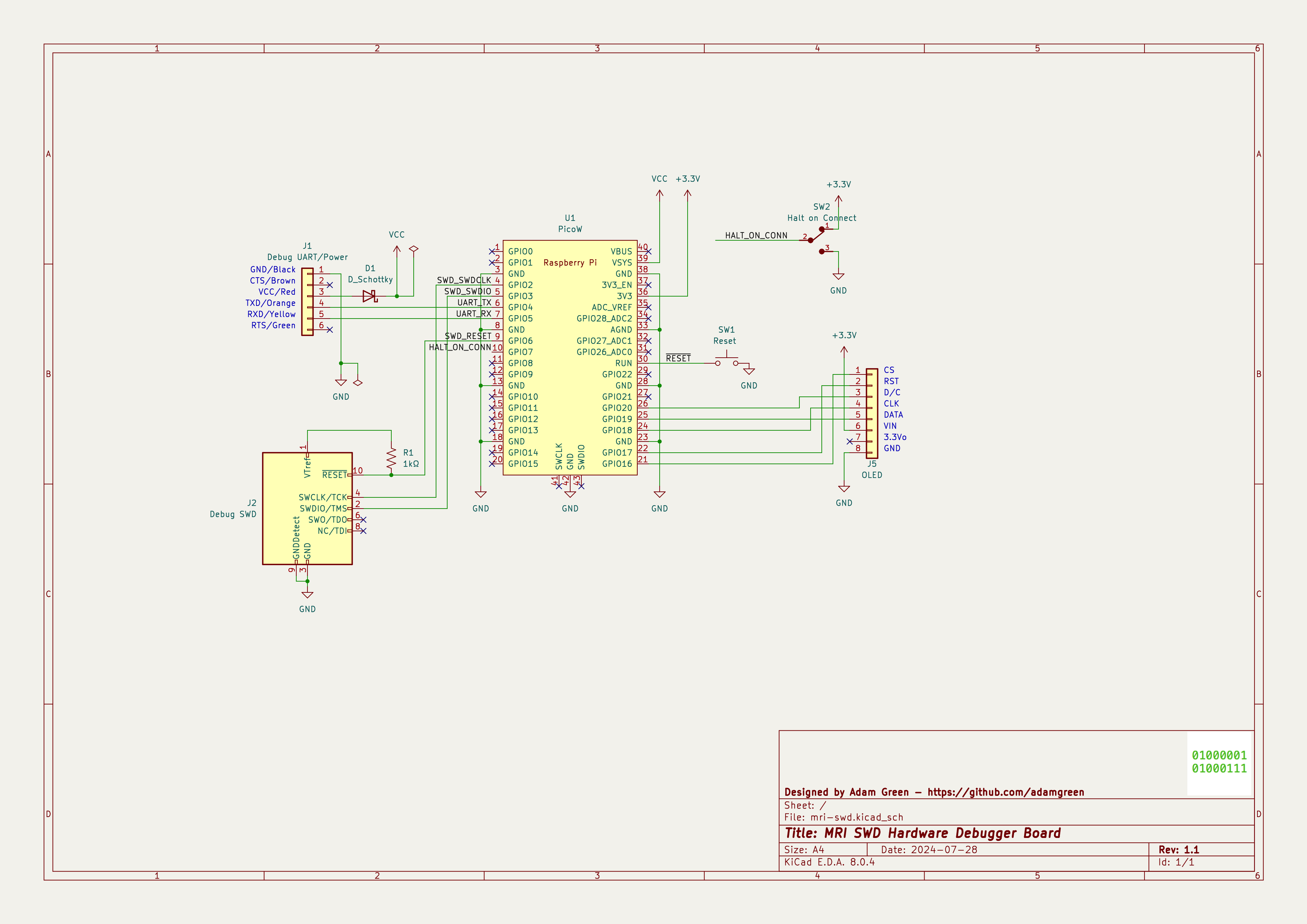
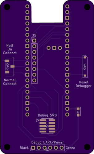
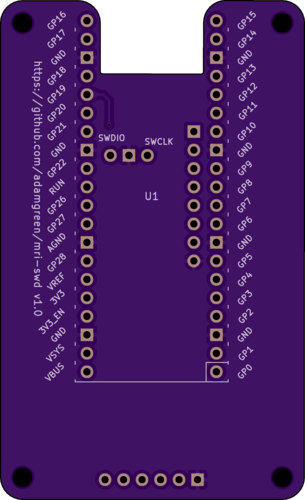
| Qty | Value | Footprint | References |
|---|---|---|---|
| 1 | 1kΩ | Resistor_SMD:R_0805_2012Metric_Pad1.20x1.40mm_HandSolder | R1 |
| 1 | D_Schottky | Diode_SMD:D_SOD-123F | D1 |
| 1 | Debug SWD | Footprints:CON10_2X5_DUK_FTSH_SAI | J2 |
| 1 | Debug UART/Power | Connector_PinHeader_2.54mm:PinHeader_1x06_P2.54mm_Vertical | J1 |
| 1 | Halt on Connect | Footprints:SW_JS102011JCQN | SW2 |
| 1 | OLED | Connector_PinHeader_2.54mm:PinHeader_1x08_P2.54mm_Vertical | J5 |
| 1 | PicoW | Footprints:RPi_PicoW_SMD_TH | U1 |
| 1 | Reset | Footprints:Adafruit-SPST-Switch-7 | SW1 |
adamgreen/mri-swd
Work In Progress! - MRI-SWD - GDB compatible hardware probe which allows debugging of Cortex-M based microcontrollers over SWD.


joeycastillo/Sensor-Watch
A board replacement for the classic Casio F-91W wristwatch

rusefi/rusefi
rusefi - GPL internal combustion engine control unit

hoglet67/RGBtoHDMI
Bare-metal Raspberry Pi project that provides pixel-perfect sampling of Retro Computer RGB/YUV video and conversion to HDMI

shanteacontrols/OpenDeck
A platform for building interactive control and sensing devices using MIDI and OSC built with Zephyr RTOS.

hackclub/OnBoard
💡 Join 1,000 teenagers and make your first PCB with a $100 grant!

dangiu/PicoMemcard
Emulating PSX Memory Card (or controller) using a Raspberry Pi Pico

OLIMEX/DIY-LAPTOP
Do It Yourself Open Source Hardware and Software Modular Hacker's Friendly Laptop
It measures 41.7 × 68.6 mm and has 2 copper layers, 1.6 mm thick.
8 parts. The full list of its parts is on this page, with links to each part's symbol and footprint where PCBKit's library has them.
From the adamgreen/mri-swd repository on GitHub, at the commit this page was made from: the board is hardware/DebugBoard/mri-swd.kicad_pcb and its schematic hardware/DebugBoard/mri-swd.kicad_sch. PCBKit opens the board in the browser, with nothing to install.
Its repository publishes it under the Apache-2.0 licence: you may reuse it on that licence's terms (keep the author's notice, and for a copyleft licence share your changes alike).