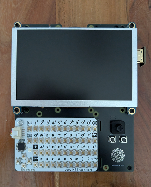
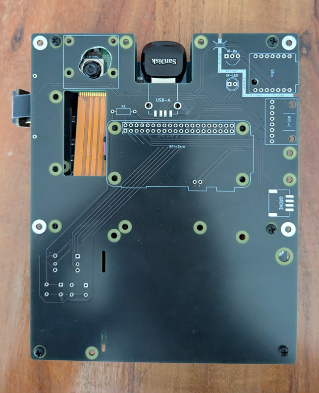
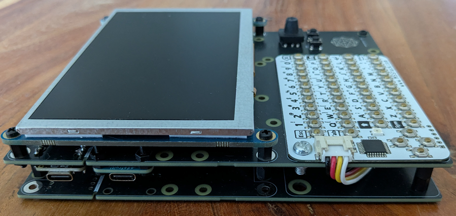
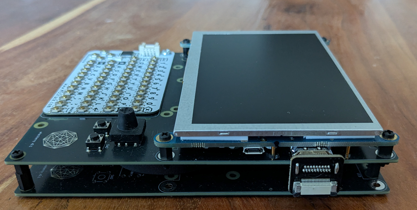
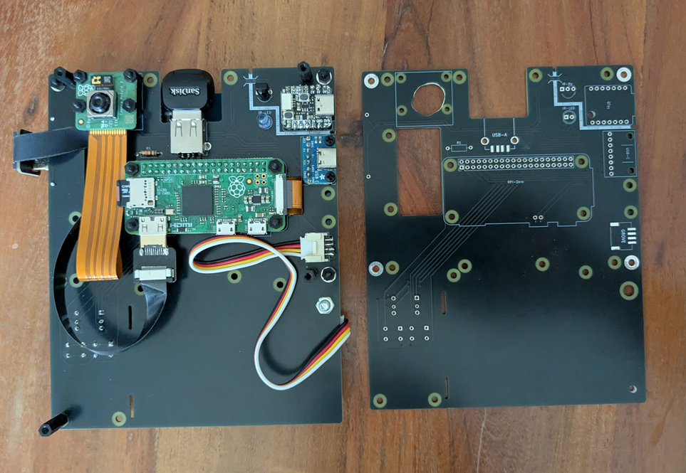
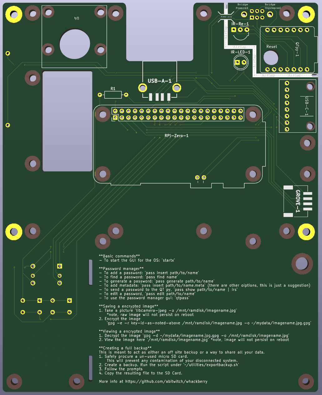
This guide assumes you have some experince with soldering. Locational references (up, down, left, right) assume the PCB is upright with the logo facing you.
Whackberry mobo is an open-source printed circuit board by abitwitch, from the abitwitch/whackberry repository on GitHub. It is a 2-layer board of 121.5 × 150 mm with 15 parts on 69 nets, routed with 236 tracks and 49 vias.
It is built around the EG2208. Its parts include 3 switches, 1 resistor and 1 IC.
Disconnected computer (with display) with no wireless connectivity on any part of the device
QWERTY keyboard with access to most standard symbols
A mouse for navigating the OS in GUI mode
A additional Micro SD card reader that can be used to create backups of passwords for storage in a secure secondary location
A Camera to take pictures that are unable to reach the internet (useful for QR backup codes of 2FA apps)
A disconnected microcontroller that is able to transmit data from the disconnected computer to another computer using a data diode
How the data diode works:
The disconnected computer has a special command for transmitting data (ir-sender). This program can take standard input in bash.
The program encrypts the input. NOTE that the hardware only suport very weak and out-of-date encryption. Although it may provide a small layer of security, it should not be relied upon. This means anyone able to read the IR led blinking from inside the case, may be able to eventually decypt the messages. This seems like a low-level risk.
The program break the message into packets then into pulses and used the IR LED light transmit the password. Since there is no way to read messages from the LED, this is a one way communication. This is the data diode and it uses the "fire and forget" principle. This means errors in reading the message is possible. A check sum is part of the protocol to account for this possible error.
On the other side of the LED there is a IR Reciever. It is connected to a microcontroller that is completely disconnected* from the raspberry PI. The only way to communicate is over the air-gap via IR (one way).
*Note that the microcontroller is connected via power (5v and Ground). This allows the disconnected computer to be powered when the microcontroller is pluged into a computer. This does technically open the possibility of side channel attacks.
The signal is recieved, decapsulated, combined, and de-crypted. The checksum is verified before decryption and the process will only continue if the checksum and decryption are successful.
When plugged into a computer, the air-gapped microcontroller acts as a keyboard and the message recieved is transmitted as keystrokes to the computer.
Setup:
To set up a device, follow the instructions in each section of this readme from top to bottom.
There PCB (Printed Circuit Board) design is included in this repository. This can be ordered online for a PCB manufacturer. If you want to forgo the case, you can order 2 boards and use the second with the one with standoffs to protect the device.
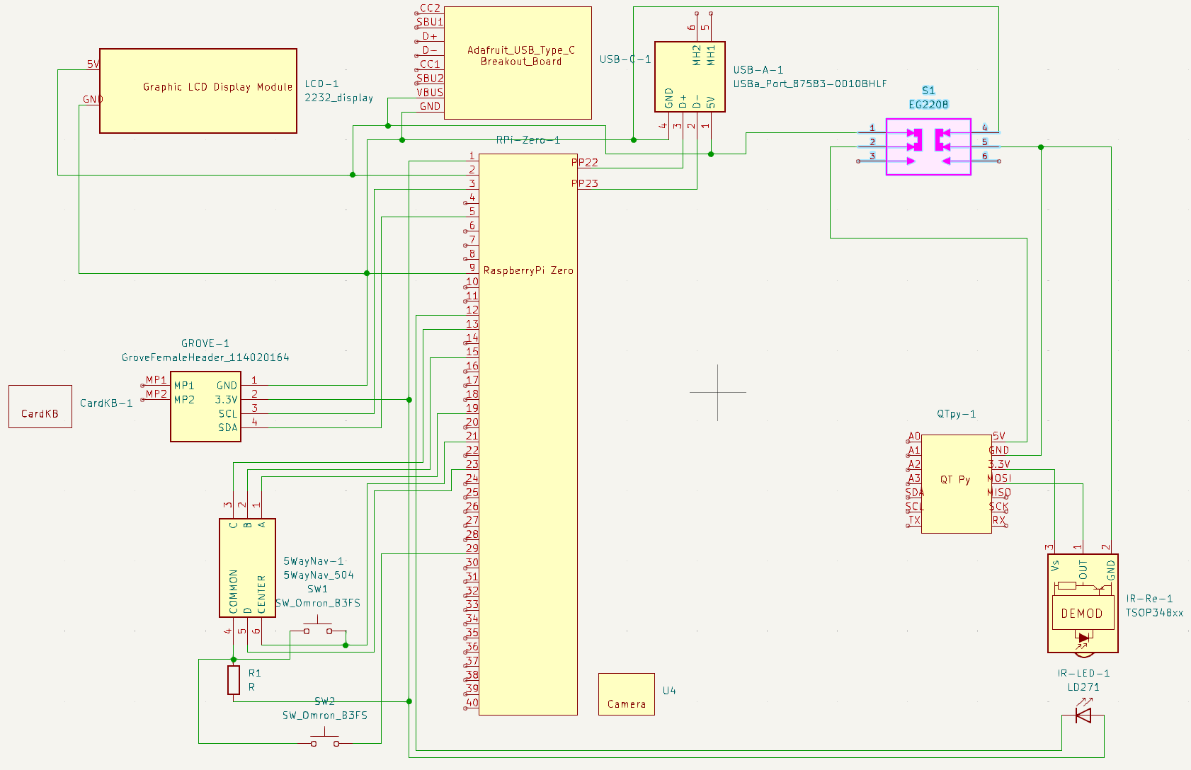
Schematic
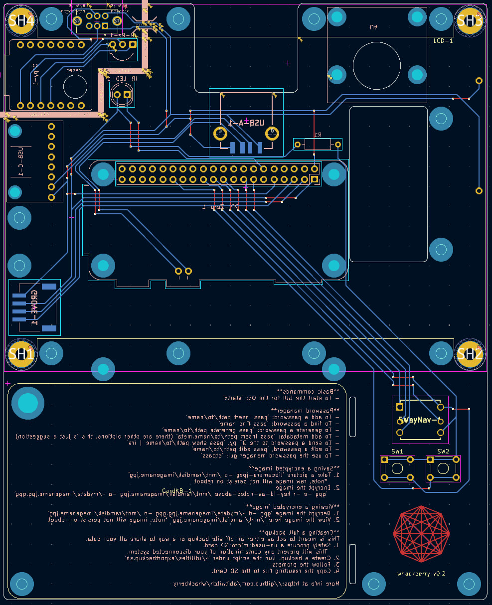
Design view
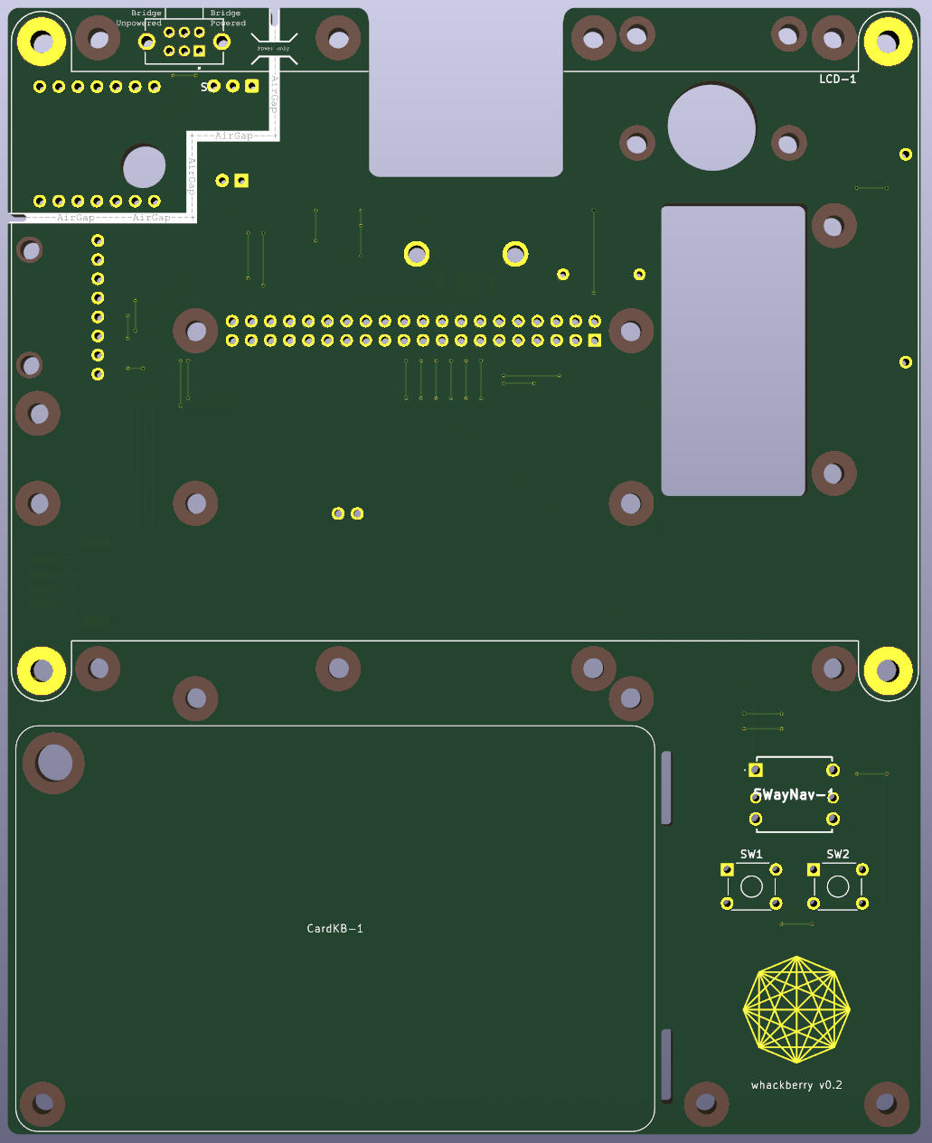
Front view
Back view
Assembly guide
This guide assumes you have some experince with soldering. Locational references (up, down, left, right) assume the PCB is upright with the logo facing you. The logo side is the front of the board, the other side is the back.
Prepare parts
Break the Male-male pin headers into 2 7 pin pieces and 1 8 pin piece
Solder the QTpy to the two 7 pin headers with the pins facing away from the side with the USB port on it.
Repeat the previous step for the Raspberry Pi Zero, and USB-c Breakout board.
Break the POGO pins into 2 single pins and 1 pieces with 2 still attatched pins.
Attach USB-c Breakout board
Use a M2.5 hex nut as a space between the USB-c breakout board and the main PCB, with the USB-c breakour board on the back of the main PCB. Secure the breakout board in place with more M2.5 nuts and screws
Clip of excess pin length from the pins of the USB-c breakout board headers and then solder the pins in place
Attach QTpy
Place the QTpy in place on the back of the main PCB
Clip of excess pin length from the pins of the QTpy headers and then solder the pins in place
Attach Raspberry Pi Zero
Solder the 2 attached pogo pins below the main headed pins in the Raspberry Pi Zero footprint. The pins should be facing the back of the board
Use 6mm long F-F hex standoffs and screws to attach the Raspberry Pi Zero fo the back of the main PCB. The pogo pins should be making contect with the Raspberry Pi Zero, and the main header pins should slightly protrude through the main PCB.
Solder all the main header pins into place.
Other soldered-in pieces
Solder the GROVE Female Header onto the back of the main PCB
Solder the USB Type-A Jack onto the back of the main PCB
Insert the 5-way nav switch on the front of the PCB and solder in the pins
Repeat step above for both buttons below the 5-wav nav switch
Insert the Resistor on the back of the main PCB, clip excess pin lenth, and solder into place
Repeat step above for the IR-Reciever and the IR LED
Attach the camera module
The mounting holes on the camera module are slightly smaller than M2.5 screws. You will either need to largen the holes are buy different hardware.
Use 6mm long F-F hex standoffs to attatch the camera to the back of the main PCB
Attach CardKB
Use the M4 nut and bolt to attach the CardKB to the front of the main PCB
Cables
Connect the Camera module to the Raspberry Pi Zero
Connect the CardKB to the main PCB GROVE header
Use the DYI HDMI cable to connect the display to the Raspberry Pi Zero
Protection plate
Only do this if you are not making a 3D printed case
Choose 4 or 5 well distributed, unused, and accessible mounting holes and insert into each a M2.5 10mm Screw into an unused PCB (with nothing else solder or attached to it)
To the back of each of the screws, screw on a 6mm long F-F hex standoff untill snug
To the still protruding screws, screw on a 8mm long F-F hex standoff untill snug
Place the this PCB on the main on being careful not to pitch any cables
Screw the two boards together with M2.5 4mm Screws into the standoffs
Setup guide
1.00: SD card setup
This part can be done on any trusted computer connected to the internet
Flash the SD card and then access the files on the SD card
Set up the display
Setup the display. Under bootfs > config.txt if accessing from a SD Card reader or \boot\config.txt if accessing from the OS, add the following lines (more info here)
text
Enable i2c. In the same config.txt file, uncomment "dtparam=i2c_arm=on". Follow instructions here
2.00: Configure the OS
I suggest doing the configuartion from another pi with internet. Plug the SD card into a internet-connected Raspberry Pi and boot it. Follow the commands to set up your account and apply any updates. You can use a less secure password if you want, the more import one will be the one you use when setting up a GPG key. Reboot the device.
Follow the instructions for "Installation from Python sources" (tested with version 4.5.8)
2.05: Copy Etherium wallet script
mkdir ~/cryptowallet
Copy cryptowallet/gen-eth-wallet.py from this repo to ~/cryptowallet/gen-eth-wallet.py on the raspberry pi
chmod +x gen-eth-wallet.py
2.06: CarKB setup
mkdir ~/cardkb, then cd ~/cardkb
Follow instructions here (Note: add sudo to modprobe uinput)
2.07: Camera Setup
Just plug and play
libcamera-hello to test
libcamera-jpeg -o /path/to/file.jpg to take a picture
2.08: Set up 5-way navi mouse
mkdir ~/navmouse, then cd ~/navmouse
Copy navmouse/mouse.py and navmouse/navmouselauncher.sh from this repo to ~/navmouse on the raspberry pi
chmod +x *
'sudo nano /etc/xdg/lxsession/LXDE-pi/autostart`
Add this line to the end of the file, then save and exit: @/home/{name of user}/navmouse/navmouselauncher.sh
TODO: Fix this section
2.09: Infrared Transmitter
Create a RAM disk for storing output:
Add newramdisk /mnt/ramdisk tmpfs rw,size=8M 0 0 to /etc/fstab (Note, you must replace each set of spaces with a tab)
Configuration
sudo nano /boot/config.txt
Add a line with dtoverlay=gpio-ir-tx,gpio_pin=18 to the file, then save and exit
sudo nano /etc/modules
Add a line with lirc_dev to the file, then save and exit
mkdir ~/ir-sender
Copy ir-protocol/ir-sender from this repo to the folder ~/ir-sender
Copy ir-protocol/ir-sender-gui from this repo to the folder ~/Desktop/ir-sender-gui
chmod +x ~/ir-sender
chmod +x ~/Desktop/ir-sender-gui
Add these lines ~/.profiletext
if [ -d "$HOME/ir-sender" ] ; then
PATH="$PATH:$HOME/ir-sender"
fi
Generate new key: ir-sender --genkey
Copy the contents of the json and use it when setting up the Infrared Reciever
For ease of use, add an alias for ir-sender
Edit ~/.bashrc
Add this line to the bottom: alias irs=ir-sender
2.10: Infrared Reciever
This part of the device is on an isolated device that emulates a keyboard when plugged into the computer.
On a PC connected to the Pico
Download circuit python for the QTPy RP2040 (link) (I used CircuitPython 9.2.6)
Download the circuit python bundle (link) (I used 'March 19, 2025 auto-release')
While holding down the BOOT button on the QTPy, connect it to the PC.
Copy the "uf2" file you downloaded in step 1 to the device. You should see INDEX.HTM and INFO_UF2.TXT there already. Wait for the device to reboot.
Unzip the folder from step 2 and copy the following folders and file to the lib folder of the QTPy.
adafruit_hid, adafruit_pixelbuf.mpy, neopixel.mpy, adafruit_rsa, adafruit_logging.mpy, adafruit_binascii, adafruit_hashlib
Copy the contents of the ir-receiver-code.py to code.py
Copy boot.py to boot.py at the top level of the QTPy
Create a new file at the top level called private_key.json and put the json contents in it generated when setting up the Infrared Transmitter
Optional: If you want a second reciever for any reason (for example, you don't want to plug the same reciever into every computer you need a password on), here's how to set up a secondary one.
Solder on a IR (Infrared) Receiver (the same one listed earlier in this project). Attach GND to GND, V to 3.3V, and OUT to GP0.
Follow the same steps above (for the main Infrared Reciever), with these minor changes
In the code.py file, change board.MOSI to board.GP0 and board.NEOPIXEL to board.GP16
In the boot.py file, change board.A0 to board.GP15
Copy the private_key.json from the original RP2040 device to this one
2.11: Copy over the utility scripts
mkdir ~/utilities
Copy utilities/exportbackup.sh from this repo to ~/utilities/exportbackup.sh on the raspberry pi
Copy utilities/importfromcsv.py from this repo to ~/utilities/importfromcsv.py on the raspberry pi
sudo chmod +x ~/utilities/*
2.12: Test the system
Power down the raspberry pi you're using for setup. Move the SD card to the offline raspberry pi.
Test the system to make sure all features work as expected
2.12: Copy any passwords to the SD card
Copy password from any existing password managers to the SD Card (make sure to place them in a appropriate folder as not to mess up the OS on the SD Card).
3.00: Finish system init (offline)
Only perform these steps when you're done setting up the device and ready to never connected to the internet again
If the SD card is still in the Raspberry Pi you were using for setup, move it to the offline Raspberry Pi Zero.
Use system for 5-10 minutes to generate entopy (try ninvaders)
mkdir ~/mydata
Set up password manager
Generate key
gpg --gen-key
Real name: user
Email: [empty]
O for okay
Enter a password (this will be the master password for the password manager). Make sure it is a secure password and do not share it.
Note the id of the key. This will be a lond alphanumberic sequence right above "uid"
Set key to never expire
gpg --edit-key key-id-as-noted-above
expire
enter 0
q to quit (and y to save changes)
pass init key-id-as-noted-above
Generate Bitcoin BTC wallet
Start electrum with this command ~/electrum/Electrum-4.5.8/run_electrum
This application will run slowly. Be prepared to wait a few minutes between screens.
Follow prompts and be sure to save the new seed to the password manager (pass). Using a password is recommended, you can generate and store one it pass, then copy it to the clipboard by using pass -c {Folder/name}
In the "Recieve" tab, create a never expiring request and save the public address to pass as well. You can use this to send money to the wallet.
Export the private keeys to pass
Under "Wallet" > "Private keys", select "Export"
Specify the file location to somewhere on /mnt/ramdisk (this way it will not presist on disk as plain text)
Add a column to the CSV titled "BurntPrivKey", and set it to "No" for all rows
Run cat /mnt/ramdisk/{filename-of-exported-keys.csv} | pass insert {Folder/name} -m
Generate Etherium ETH wallet
Run the command python3 ~/cryptowallet/gen-eth-wallet.py
Enter both the private key and the public key to the pass password manager
Using the system
Basic commands
To start the GUI for the OS: startx
Password manager
To add a password: pass insert path/to/name
To find a password: pass find name
To generate a password: pass generate path/to/name
To find a password: pass find myaccount
To add metadata: pass insert path/to/name.meta (there are other oiptions, this is just a suggestion)
To send a password to the QT py, pass show path/to/name | irs
To edit a password, pass edit path/to/name
To use the password manager gui: qtpass
Saving a encrypted image
Take a picture libcamera-jpeg -o /mnt/ramdisk/imagename.jpg *note, raw image will not persist on reboot
Encrypt the image gpg -e -r key-id-as-noted-above /mnt/ramdisk/imagename.jpg -o ~/mydata/imagename.jpg.gpg
Viewing a encrypted image
Decrypt the image gpg -d ~/mydata/imagename.jpg.gpg -o /mnt/ramdisk/imagename.jpg
View the image here /mnt/ramdisk/imagename.jpg *note, image will not persist on reboot
Creating a full backup
This is meant to act as either an off site backup or a way to share all your data.
Safely procure a un-used micro SD card. This will prevent any contamination of your disconnected system.
Create a backup. Run the script under ~/utilities/exportbackup.sh
Follow the prompts. Note that with a lot of passwords, the "Exporting passwords" step can take a long time to run (last time was ~30 minutes for me).
Copy or move the resulting file to the SD Card.
Import csv to password manager
Modify the script here: ~/utilities/importfromcsv.py to match the fields in the CSV from your password manager
Run python3 ~/utilities/importfromcsv.py /path/to/passwords.csv
After successfully importing the passwords, delete the csv rm /path/to/passwords.csv
Sending recieving Bitcoin (btc)
You can send and recieve btc without exposing your private keys to the internet.
Recieving:
Open Electrum
Go to the recieving tab and create a request. Make one of your "burnt" addresses it not being used. Send btc using any app to that address.
Sending:
Option 1: signing a transaction (requires manual transcription)
On a computer connected to the internet
Install Electrum and wait for it to sync
Go to File > New/Restore
Select "Import Bitcoin addresses or private keys"
Enter the public addess (NOT the private keys!) from the Whackberry device (you can do that using this command: echo bitcoin_public_address | irs)
Under the send tab, enter the address you want to send to, the amount, then click "Pay..."
Set the transation fee and click "OK"
Click the share button and "Copy to clipboard..." (paste in a text editor)
On the Whackberry
Open Electrum
On the top menu, "Tools" > "Load transation" > "From text"
The camera will not work with the Electrum app, so you will have to manually copy the transation to the whackberry (make no mistakes, good luck).
"Sign" the transation
Click the share button and "Copy to clipboard..." (recommend pasting it somewhere like /mnt/ramdisk/txn.txt)
Transfer that file back to the internet connected computer: cat /mnt/ramdisk/txn.txt | irs (you'll want to open a text editor on the internet connected computer to capture the contents of the file)
On a computer connected to the internet
In Electrum, on the top menu, "Tools" > "Load transation" > "From text"
Paste in the transation contents you transfered from the whackberry.
Click "Broadcast"
Option 2: Burning a Private key
Mark the private key as "burnt" on the Whackberry: pass edit path/to/privatekeys. I recommend labeling it in the Electrum GUI too (under the addresses tab)
Copy the ONLY THE BURNT private keys to a internet connected computer
Test a command to ONLY get the burnt addresses: pass show path/to/privatekeys | grep ,Yes (Make 100% sure it's only outputing the private keys you want to burn)
Copy the ket to the internet connected computer: ``pass show path/to/privatekeys | grep ,Yes | irs`
On the internet connected computer
Follow steps 1.1 to 1.3 under "Option 1"
Enter the private key
Transfer all the bitcoin to your intended addresses. Keep in mind you can also transfer to other addresses on the Whackberry that are not yet burnt.
Accessing cold wallets (online)
Use ir-sender to send the target private key from the disconnected raspberry pi to a computer connect to the internet. Make sure to note any private keys or seeds being transfered. They are no longer totaly secure.
Open the application and when prompted, select "Standard wallet" then "I already have a seed"
Enter the seed for the Bitcoin BTC wallet.
You can use the "Send" tab to send to any address. Start with a small amount to make sure everything is working.
For Etherium ETH:
You can use any wallet that supports importing private keys to access the BTC. I'll include instructions for MetaMask Firefox Extension (v12.6.2) below.
Once on the main account page, click the account dropdown at the top of the screen
Select "Add account or hardware wallet" then "Import account"
Enter the private key for Etherium ETH.
You can use the "Send" button to send to any address. Start with a small amount to make sure everything is working.
Case
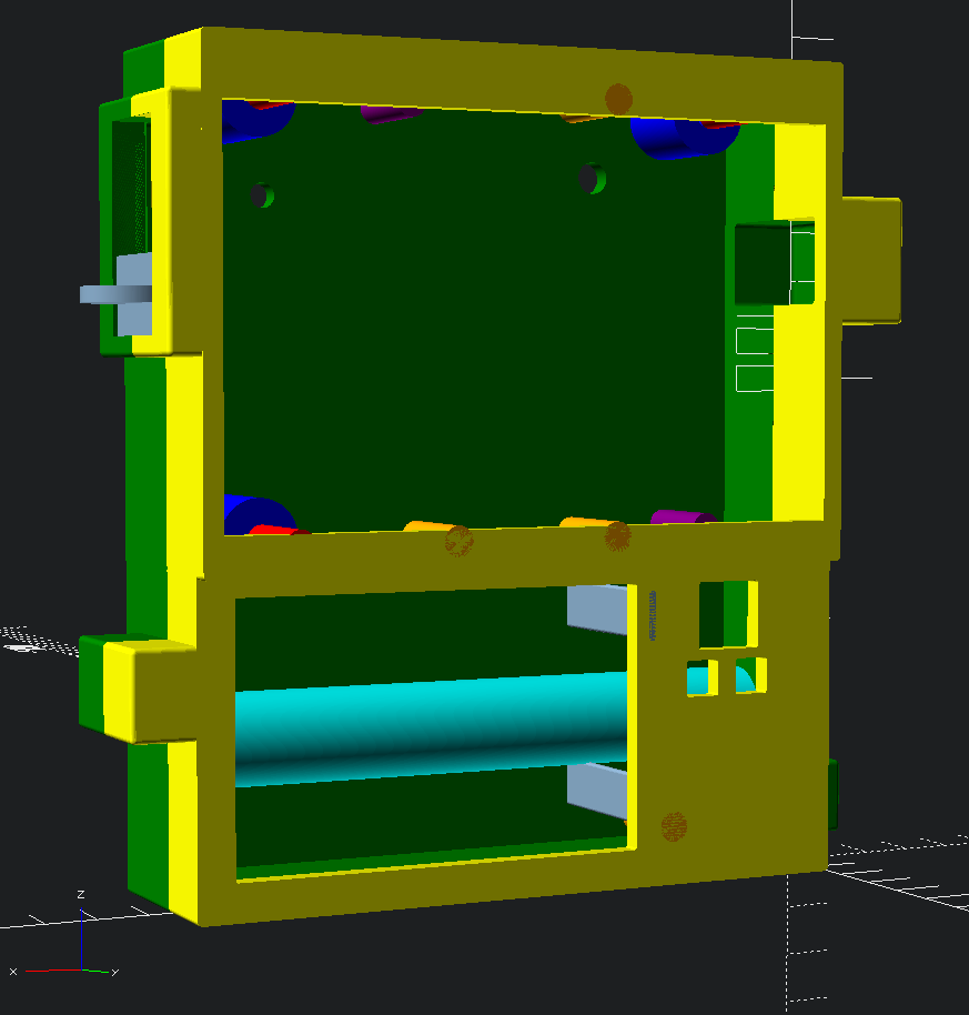
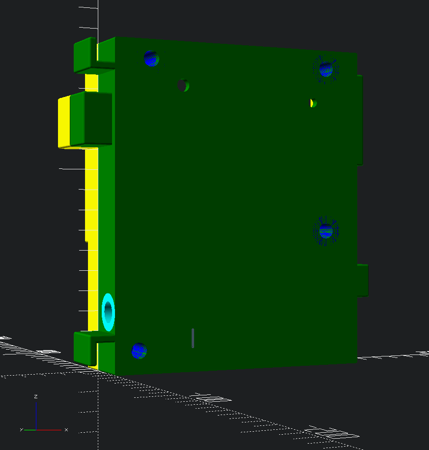
There is a 3D printable case included in this repository to help manage the cables and protect the devices. This case is yet to be printed and tested, so it likely we need to be altered and iterated.
Front of case
Back of case
Trouble shooting
Opening the camera causes the system to crash
This is likely a power issue to the camera. First try adding these two lines to the "/boot/config.txt" file; over_voltage=2 and force_turbo=1. If the problem persists, lower the blacklight one the display by cutting the trace in between the two pads labeled "Open for -25mA" (more info here).
It measures 121.5 × 150 mm and has 2 copper layers, 1.6 mm thick.
What parts does the Whackberry mobo use?
15 parts, built around the EG2208. The full list of its parts is on this page, with links to each part's symbol and footprint where PCBKit's library has them.
Where can I download the Whackberry mobo KiCad files?
From the abitwitch/whackberry repository on GitHub, at the commit this page was made from: the board is pcb/whackberry_mobo/whackberry_mobo.kicad_pcb and its schematic pcb/whackberry_mobo/whackberry_mobo.kicad_sch. PCBKit opens the board in the browser, with nothing to install.
Can I use the Whackberry mobo design in my own project?
Its repository states no licence, so its author keeps all rights: ask abitwitch before reusing the design.


 abitwitch/whackberry