
2 layers60 × 30 mm
Controller
google/mozc-devices
Circuit diagrams and firmware source code for Gboard DIY keyboards
11 parts3kApache-2.0

A transistor-based Astable Multivibrator designed and implemented using KiCad. This project demonstrates the design, PCB layout, and working of a free-running multivibrator capable of generating a continuous square-wave…
Astable is an open-source printed circuit board by abhayiitj2027, from the abhayiitj2027/AstableMultivibrator repository on GitHub. It is a 2-layer board of 60.5 × 58 mm with 11 parts on 7 nets, routed with 55 tracks and 0 vias.
Its parts include 4 resistors, 2 capacitors, 2 diodes and 2 transistors.
A transistor-based Astable Multivibrator designed and implemented using KiCad. This project demonstrates the design, PCB layout, and working of a free-running multivibrator capable of generating a continuous square-wave output. The circuit alternately switches two LEDs ON and OFF with an approximate oscillation period of 0.5 seconds.
An astable multivibrator is a free-running oscillator that continuously switches between two stable states without requiring any external trigger. It is widely used in timing circuits, LED flashers, clock pulse generators, and waveform generation applications.
This project includes:
| Parameter | Value |
|---|---|
| Oscillator Type | Astable Multivibrator |
| Supply Voltage | 5–9 V DC |
| Oscillation Period | ≈ 0.5 s |
| Frequency | ≈ 2 Hz |
| Output Waveform | Square Wave |
| Component | Specification | Quantity |
|---|---|---|
| NPN Transistor | BC547 | 2 |
| Timing Capacitor | 8.2 µF | 2 |
| Collector Resistor | 1 kΩ | 2 |
| Base Resistor | 47 kΩ | 2 |
| LED | 5 mm Red | 2 |
| Battery Connector | 2-Pin | 1 |
The circuit consists of two NPN transistors connected in a cross-coupled configuration through capacitors and resistors.
The oscillation period is approximately given by:
[ T \approx 1.4RC ]
For this design:
Therefore,
[ T \approx 1.4 \times 47,000 \times 8.2 \times 10^{-6} \approx 0.54 \text{ s} ]
which is approximately 0.5 seconds.
The PCB includes:
AstableMultivibrator/
│
├── PCB/
│   ├── astable.kicad_pcb

│   └── astable.kicad_sch
│
├── Images/
│   ├── pcb_layout.jpeg
│   └── pcb_3d.jpeg
│
└── README.md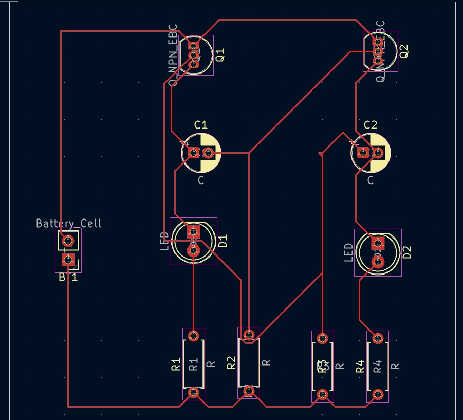
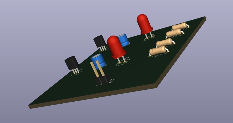
Abhay
GitHub: https://github.com/abhayiitj2027
This project is intended for educational and learning purposes. You may choose to add an open-source license such as the MIT License if you plan to distribute it publicly.
| Qty | Value | Footprint | References |
|---|---|---|---|
| 4 | R | Resistor_THT:R_Axial_DIN0207_L6.3mm_D2.5mm_P7.62mm_Horizontal | R1, R2, R3, R4 |
| 2 | C | Capacitor_THT:CP_Radial_D5.0mm_P2.00mm | C1, C2 |
| 2 | LED | LED_THT:LED_D5.0mm | D1, D2 |
| 2 | Q_NPN_EBC | Package_TO_SOT_THT:TO-92_Inline | Q1, Q2 |
| 1 | Battery_Cell | Connector_PinHeader_2.54mm:PinHeader_1x02_P2.54mm_Vertical | BT1 |
google/mozc-devices
Circuit diagrams and firmware source code for Gboard DIY keyboards


FrameworkComputer/ExpansionCards
Reference designs and documentation to create Expansion Cards for the Framework Laptop

hoglet67/RGBtoHDMI
Bare-metal Raspberry Pi project that provides pixel-perfect sampling of Retro Computer RGB/YUV video and conversion to HDMI

hackclub/OnBoard
💡 Join 1,000 teenagers and make your first PCB with a $100 grant!


tardate/LittleArduinoProjects
a collection of "Little Electronic & Arduino Projects", most involving electronics or an Arduino in one way or another!

basilfx/TRADFRI-Hacking
Hacking IKEA TRÅDFRI products, such as light bulbs, window blinds and other accessories.
It measures 60.5 × 58 mm and has 2 copper layers, 1.6 mm thick.
11 parts. The full list of its parts is on this page, with links to each part's symbol and footprint where PCBKit's library has them.
From the abhayiitj2027/AstableMultivibrator repository on GitHub, at the commit this page was made from: the board is astablePCB/astable.kicad_pcb and its schematic astablePCB/astable.kicad_sch. PCBKit opens the board in the browser, with nothing to install.
Its repository states no licence, so its author keeps all rights: ask abhayiitj2027 before reusing the design.