2 layers40 × 20 mm

 aayushimaginator/DC-DC-converter
Open-loop 12 V boost converter (20 kHz, discrete) designed in KiCad, with schematic, PCB and Gerbers
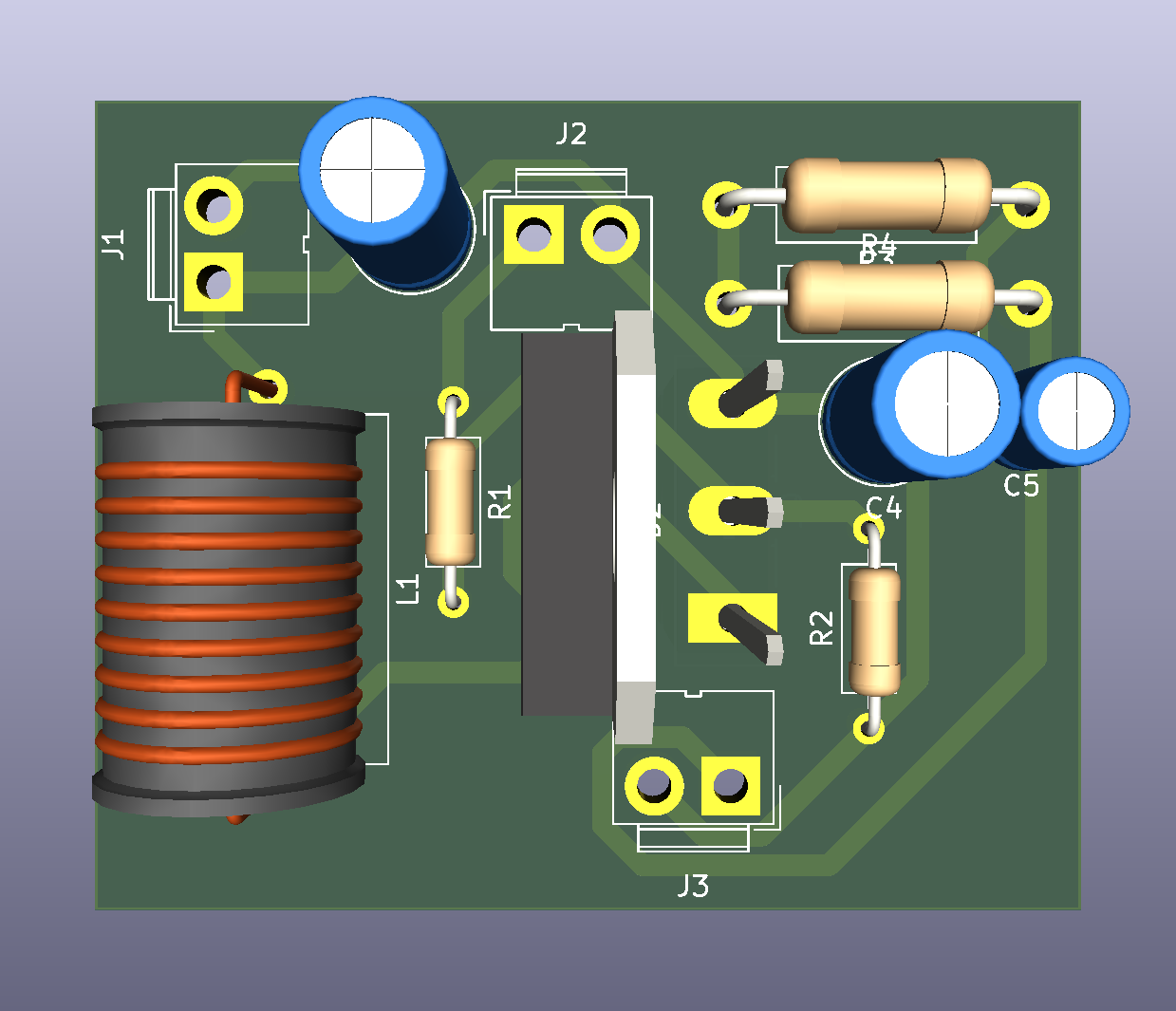
Buckboostf is an open-source printed circuit board by aayushimaginator, from the aayushimaginator/DC-DC-converter repository on GitHub. It is a 2-layer board of 50 × 41 mm with 13 parts on 7 nets, routed with 75 tracks and 0 vias.
Its parts include 4 resistors, 3 capacitors, 3 connectors, 1 diode and 1 transistor. It belongs with the power boards of this library.
A non-isolated boost (step-up) DC-DC converter built from discrete components, designed in KiCad. Made for EE306 Tinkering Lab II at NIT Goa.
| Parameter | Value |
|---|---|
| Topology | Non-isolated boost, open loop |
| Input voltage | 12 V |
| Output voltage | 13-24 V (set by duty cycle) |
| Switching frequency | 20 kHz |
| Measured efficiency | ~91 % |
| Gate drive | PWM from a function generator, no controller IC |
| Part | Value |
|---|---|
| Inductor | 319 uH, iron-powder core |
| MOSFET | IRFZ44N (55 V, 49 A) |
| Diode | MBRF20100SCT Schottky (100 V, 20 A) |
| Capacitors | 220 uF, 3 uF |
| Gate resistor (R1) | 47 ohm |
| Gate pull-down (R2) | 10 kohm |
| Output resistors (R3, R4) | 200 ohm each |
Ideal CCM relation: Vout = Vin / (1 - D)
buckboostf/ has the KiCad project (.kicad_sch, .kicad_pcb), Gerbers and drill files, ready to send to a fab.
KiCad, LTspice
Aayush, EEE @ NIT Goa
| Qty | Value | Footprint | References |
|---|---|---|---|
| 3 | Conn_01x02_Pin | Connector:JWT_A3963_1x02_P3.96mm_Vertical | J1, J2, J3 |
| 2 | 200 | Resistor_THT:R_Axial_DIN0411_L9.9mm_D3.6mm_P15.24mm_Horizontal | R3, R4 |
| 2 | 220u | Capacitor_THT:C_Radial_D6.3mm_H11.0mm_P2.50mm | C4, C6 |
| 1 | 10000 | Resistor_THT:R_Axial_DIN0207_L6.3mm_D2.5mm_P10.16mm_Horizontal | R2 |
| 1 | 319u | Inductor_THT:L_Axial_L17.5mm_D12.0mm_P20.32mm_Horizontal_Vishay_IM-10-46 | L1 |
| 1 | 3u | Capacitor_THT:C_Radial_D4.0mm_H7.0mm_P1.50mm | C5 |
| 1 | 47 | Resistor_THT:R_Axial_DIN0207_L6.3mm_D2.5mm_P10.16mm_Horizontal | R1 |
| 1 | D_Schottky_AKA | Package_TO_SOT_THT:TO-218-3_Vertical | D2 |
| 1 | NMOS | Package_TO_SOT_THT:TO-247-3_Vertical | Q1 |


samyk/magspoof
A portable device that can spoof/emulate any magnetic stripe, credit card or hotel card "wirelessly", even on standard magstripe (non-NFC/RFID) readers.

fossasia/pslab-scripts
Pocket Science Lab - Scripts for Sensor Experiments


willem-pennings/balancing-cube
A cube that balances itself in a corner or edge using reaction wheels

VoronDesign/Voron-Hardware
Cool Hardware designed by the Voron Design group

hoglet67/RGBtoHDMI
Bare-metal Raspberry Pi project that provides pixel-perfect sampling of Retro Computer RGB/YUV video and conversion to HDMI
It measures 50 × 41 mm and has 2 copper layers, 1.6 mm thick.
13 parts. The full list of its parts is on this page, with links to each part's symbol and footprint where PCBKit's library has them.
From the aayushimaginator/DC-DC-converter repository on GitHub, at the commit this page was made from: the board is buckboostf/buckboostf.kicad_pcb and its schematic buckboostf/buckboostf.kicad_sch. PCBKit opens the board in the browser, with nothing to install.
Its repository states no licence, so its author keeps all rights: ask aayushimaginator before reusing the design.