2 layers98.8 × 97.4 mm
NeOSensorV4 panel
fthiebolt/neOCampus-arduino
neOCampus Arduino | home of the neOSensors end-devices
278 parts5

 AaronC81/bfg
Basic Function Generator - a simple function generator for embedded electronics
Function generator is an open-source printed circuit board by AaronC81, from the AaronC81/bfg repository on GitHub. It is a 2-layer board of 89.9 × 71 mm with 25 parts on 39 nets, routed with 160 tracks and 13 vias.
It is built around the ATMEGA328P-PU and AD8052M/TR. Its parts include 9 resistors, 5 ICs, 3 capacitors, 2 connectors and 1 switch. It belongs with the AVR (ATmega, ATtiny) boards of this library.


The BFG is a small, minimalistic function generator based around the AD9833, controlled by an ATmega328P with a lovely little OLED display and rotary encoder.
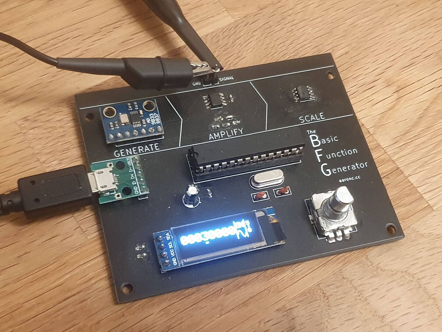
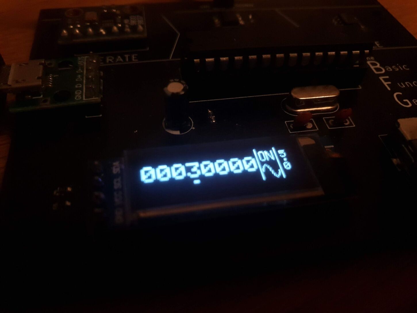
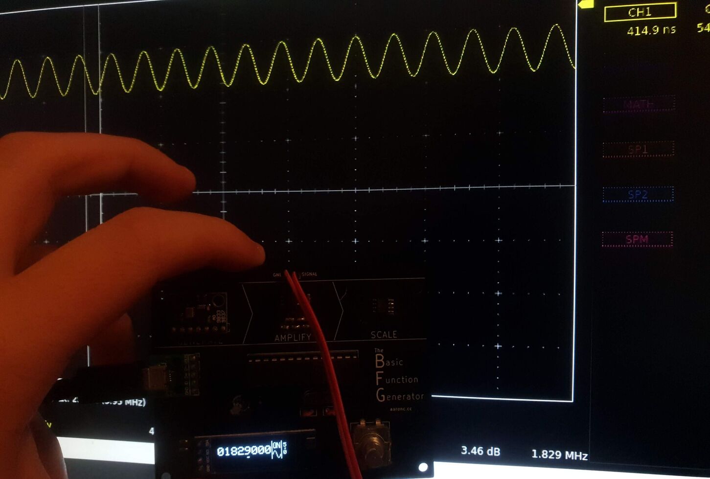
At high frequencies (>2MHz) the range of voltages begins to narrow; for example, a sine wave at 5MHz set to an amplitude of 5V only actually oscillates between about 1.5V and 4V. These frequencies are a tad much for my poor USB oscilloscope to handle, so I can't accurately measure the practical limits.
I built this for two main reasons:
As the rather lovely silkscreen on the board suggests, functions are generated by three steps:
cad contains KiCad files for the PCB.
firmware contains a platform.io project for the ATmega328P's firmware.
| Qty | Value | Footprint | References |
|---|---|---|---|
| 4 | 4.7k | Resistor_SMD:R_0603_1608Metric_Pad1.05x0.95mm_HandSolder | R1, R2, R3, R12 |
| 3 | 4.7 | Resistor_SMD:R_0603_1608Metric_Pad1.05x0.95mm_HandSolder | R9, R10, R11 |
| 2 | 22pF | Capacitor_THT:C_Disc_D5.0mm_W2.5mm_P2.50mm | C2, C3 |
| 1 | 10 | Resistor_SMD:R_0603_1608Metric_Pad1.05x0.95mm_HandSolder | R8 |
| 1 | 10uF | Capacitor_THT:CP_Radial_D5.0mm_P2.50mm | C1 |
| 1 | 16MHz | Crystal:Crystal_HC49-4H_Vertical | Y1 |
| 1 | 680 | Resistor_SMD:R_0603_1608Metric_Pad1.05x0.95mm_HandSolder | R7 |
| 1 | AD8052 | Package_SO:SOIC-8_3.9x4.9mm_P1.27mm | U5 |
| 1 | AD9833_Breakout | Connector_PinSocket_2.54mm:PinSocket_1x07_P2.54mm_Vertical | U4 |
| 1 | ATmega328P-PU | Package_DIP:DIP-28_W7.62mm_Socket | U1 |
| 1 | Conn_01x02_Female | Connector_PinSocket_2.54mm:PinSocket_1x02_P2.54mm_Vertical | J2 |
| 1 | MCP4131 | Package_SO:SOIC-8_3.9x4.9mm_P1.27mm | U3 |
| 1 | Rotary_Encoder_Switch | Rotary_Encoder:RotaryEncoder_Alps_EC12E-Switch_Vertical_H20mm | SW1 |
| 1 | SSD1306_128x32 | Connector_PinSocket_2.54mm:PinSocket_1x04_P2.54mm_Vertical | U2 |
| 1 | USB_B_Micro_NoShield | Connector_PinSocket_2.54mm:PinSocket_1x05_P2.54mm_Vertical | J1 |
The 21 most common of 25 parts.
It measures 89.9 × 71 mm and has 2 copper layers, 1.6 mm thick.
25 parts, built around the ATMEGA328P-PU and AD8052M/TR. The full list of its parts is on this page, with links to each part's symbol and footprint where PCBKit's library has them.
From the AaronC81/bfg repository on GitHub, at the commit this page was made from: the board is cad/function-generator.kicad_pcb. PCBKit opens the board in the browser, with nothing to install.
Its repository states no licence, so its author keeps all rights: ask AaronC81 before reusing the design.
fthiebolt/neOCampus-arduino
neOCampus Arduino | home of the neOSensors end-devices

zmaker/arduino_cookbook
gli sketch del nuovo progetto Arduino Cookbook e dei video di YouTube

coseyfannitutti/discipad
17-key numpad assembled with only through hole components, including usb type-c

matthewcieplak/super-sixteen
Code and schematics for the Super Sixteen Eurorack sequencer

coseyfannitutti/romeo
Staggered 40% keyboard pcb that can be assembled with only through hole components, including USB Type-C

mattybrad/drumkid
Version 4 was the first successful working design, with full code, schematics, Gerbers, etc available on GitHub.


leomil72/LM80C
A Z80-based homebrew computer withTMS9918, AY-3-8910, Z80 CTC, Z80 PIO, and Z80 SIO