


2 layers145 × 100 mm

 aaravpatel0/DroneInterception
if yk yk
Drone PCB is an open-source printed circuit board by aaravpatel0, from the aaravpatel0/DroneInterception repository on GitHub. It is a 2-layer board of 23 × 35 mm with 24 parts on 13 nets, routed with 31 tracks and 6 vias.
Its parts include 7 connectors and 4 transistors. It belongs with the robots and motor control boards of this library.
This is my drone tracking and turret project. The main goal was to detect a drone with a camera, estimate where it is in 3D space, and move a pan/tilt turret so the camera stays pointed at it.
I am Aarav Patel. I started this project as a computer vision turret, but it turned into a bigger system while I was building it. I worked on the YOLO detector, the live tracker, the Pico turret firmware, the CAD, and two custom PCBs. I also tried controlling a small commercial drone through its controller, but that got messy, so I moved toward custom electronics for the drone frame instead.
The project is not a finished product. It is a working prototype and a record of what I built, tested, changed, and still need to finish.
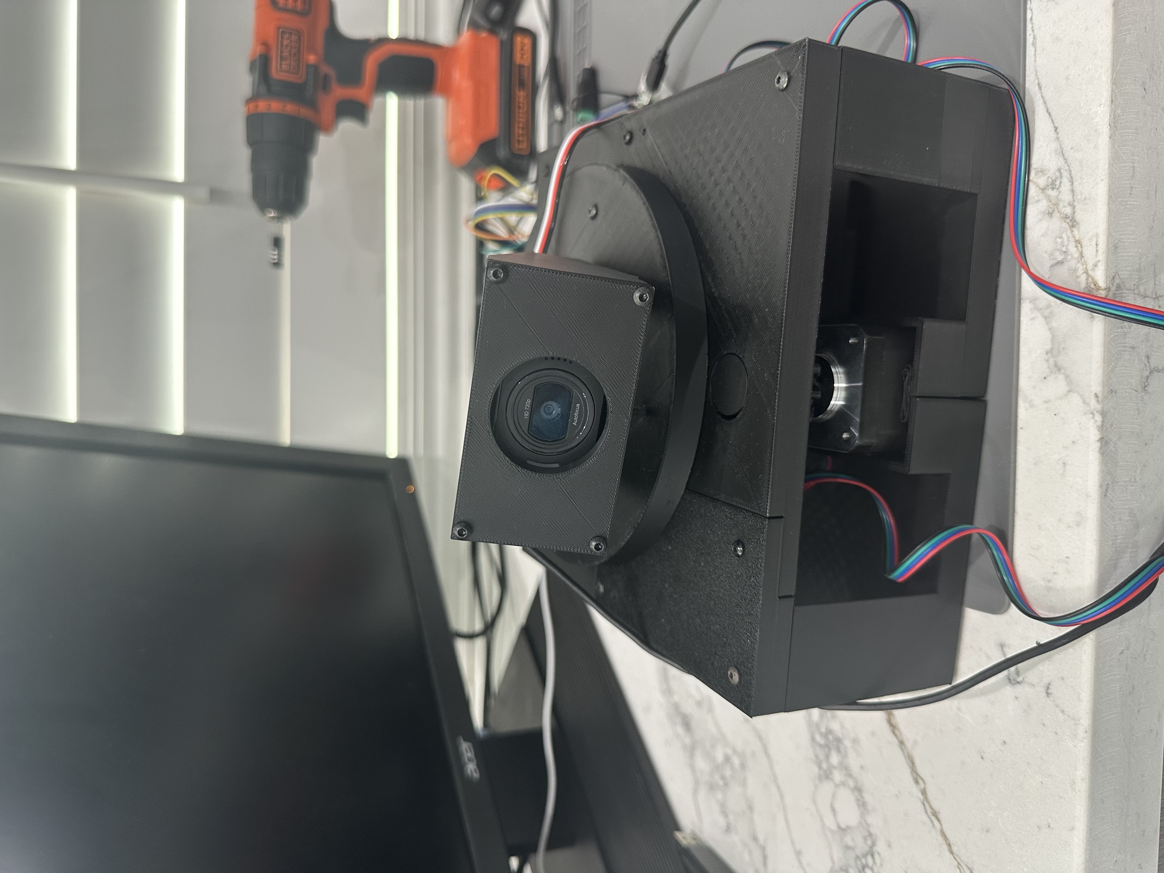
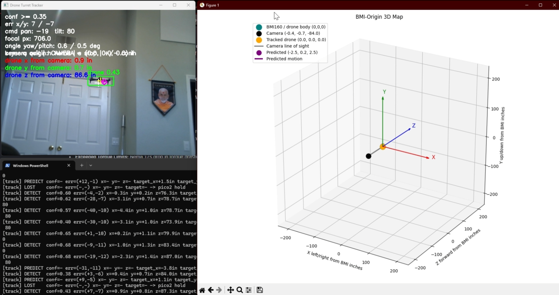
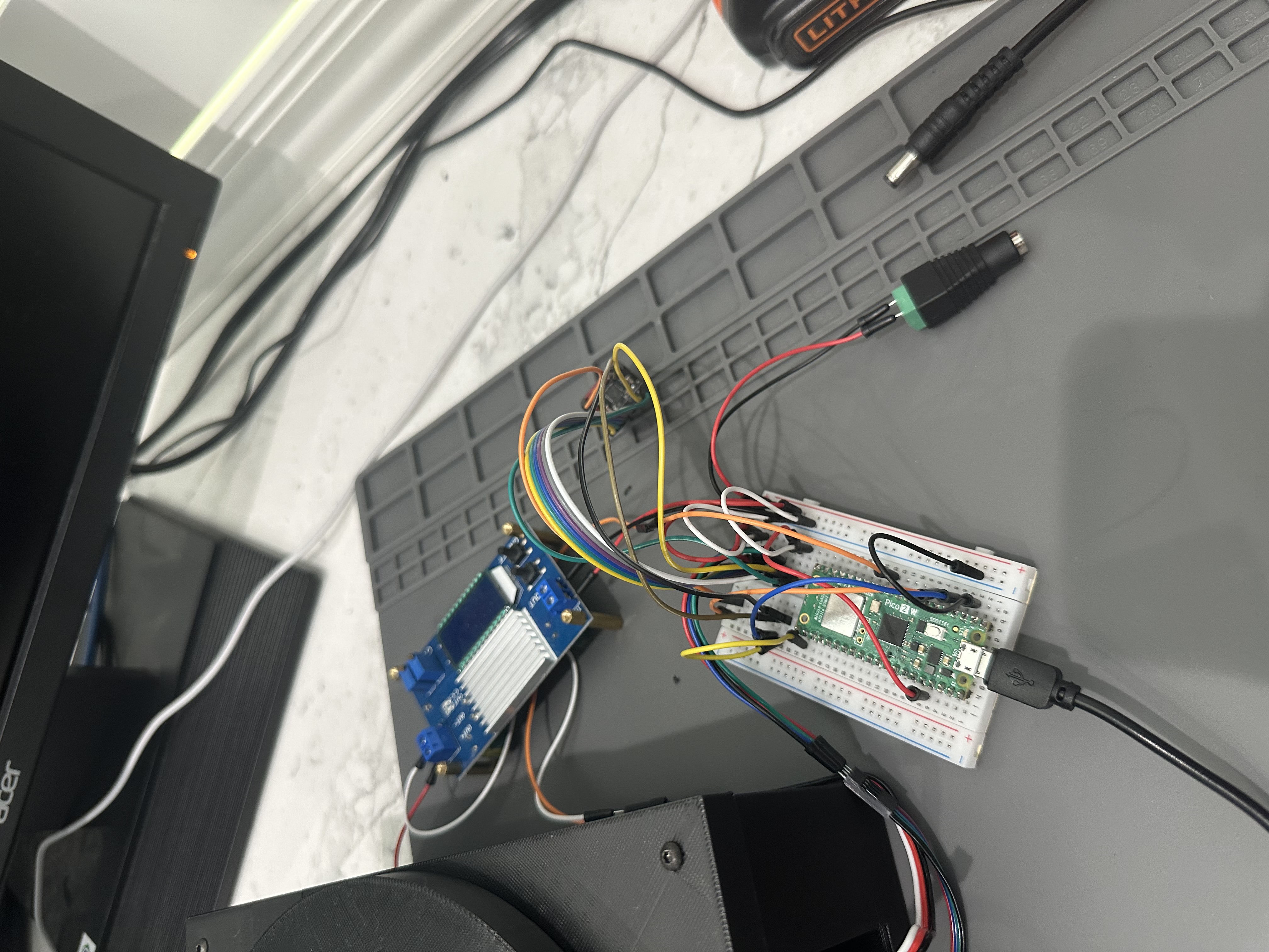
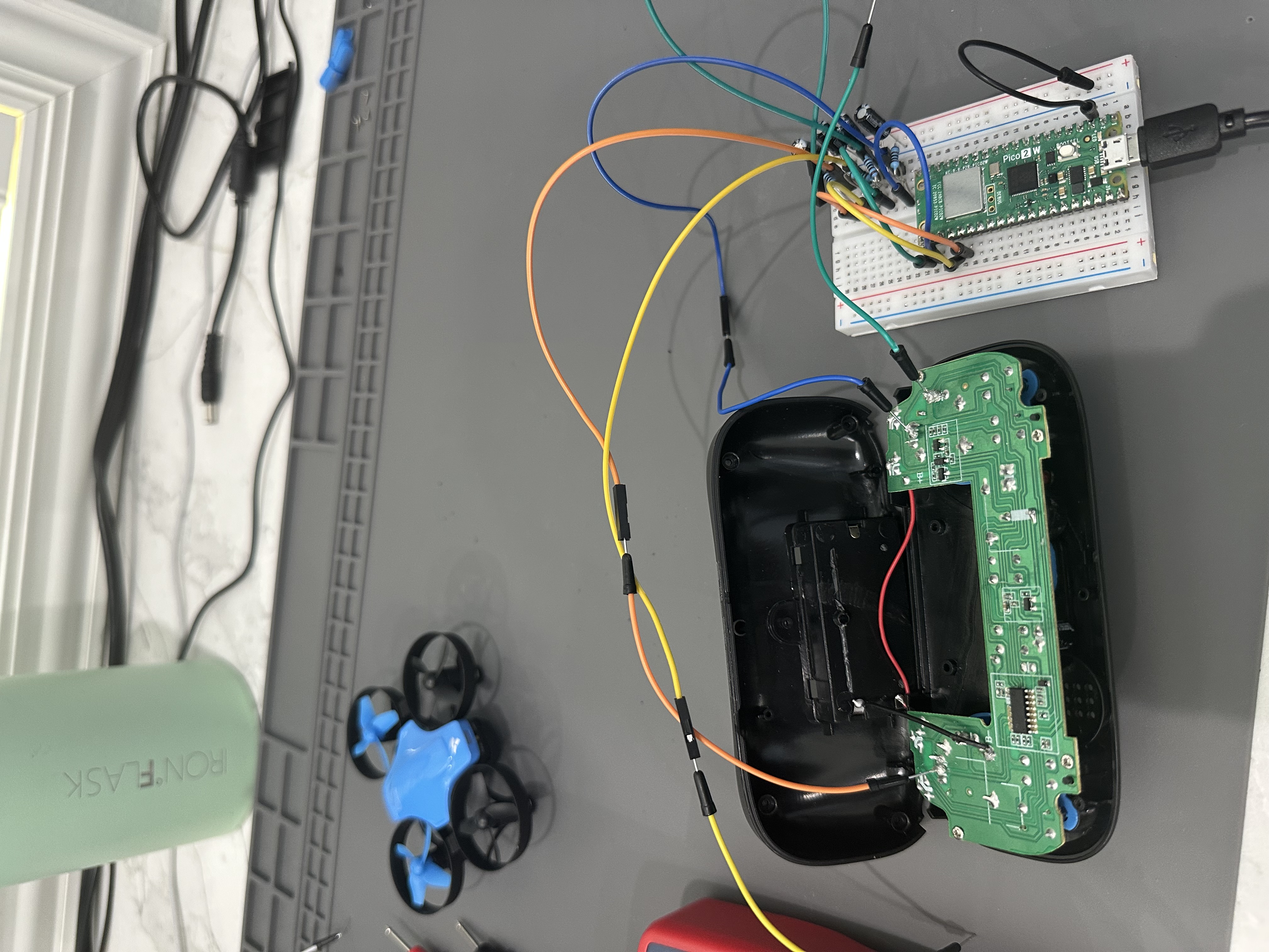
| Demo | What it shows | Repo file | Drive link |
|---|---|---|---|
| YouTube project demo | Main video for the project | - | Watch on YouTube |
| Live turret tracking | The physical turret tracking a detected drone | - | Drone Tracking Turret.mp4 |
| Detection proof of concept | Camera detection and tracking test | - | Proof of Concept - Drone Tracked.mp4 |
| Fast follow simulation | Simulated drone following a target | MP4 / GIF | Drive MP4 / Drive GIF |
| Orbit simulation | Simulated drone orbiting around the target | MP4 / GIF | Drive MP4 / Drive GIF |
| Safe standoff simulation | Simulated follow behavior that keeps distance | MP4 / GIF | Drive MP4 / Drive GIF |
| Full ship folder | Videos, previews, and extra files | - | Google Drive folder |
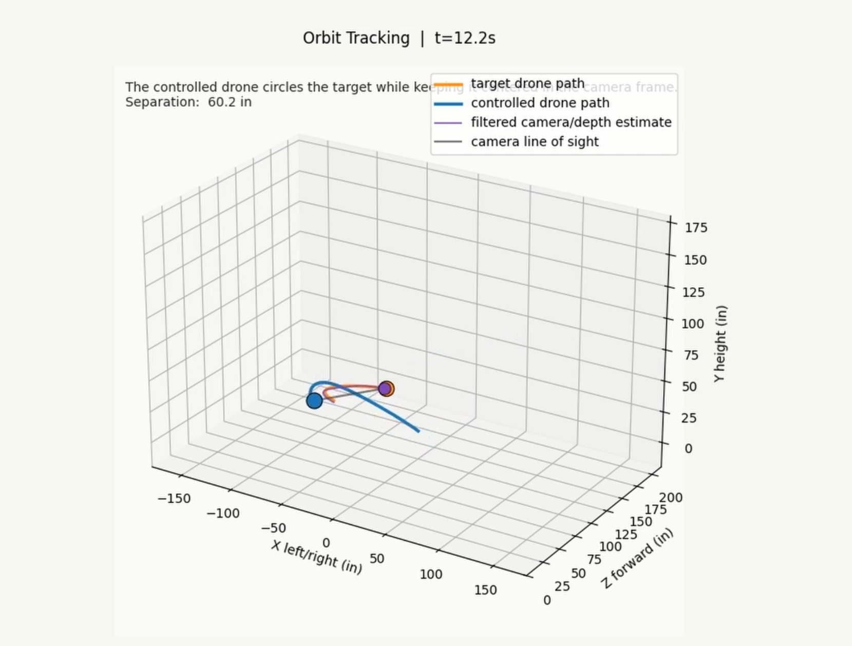
The simulation files are here:
To regenerate the simulation clips:
cd C:\Users\aptcs\Downloads\Projects\DroneDetection
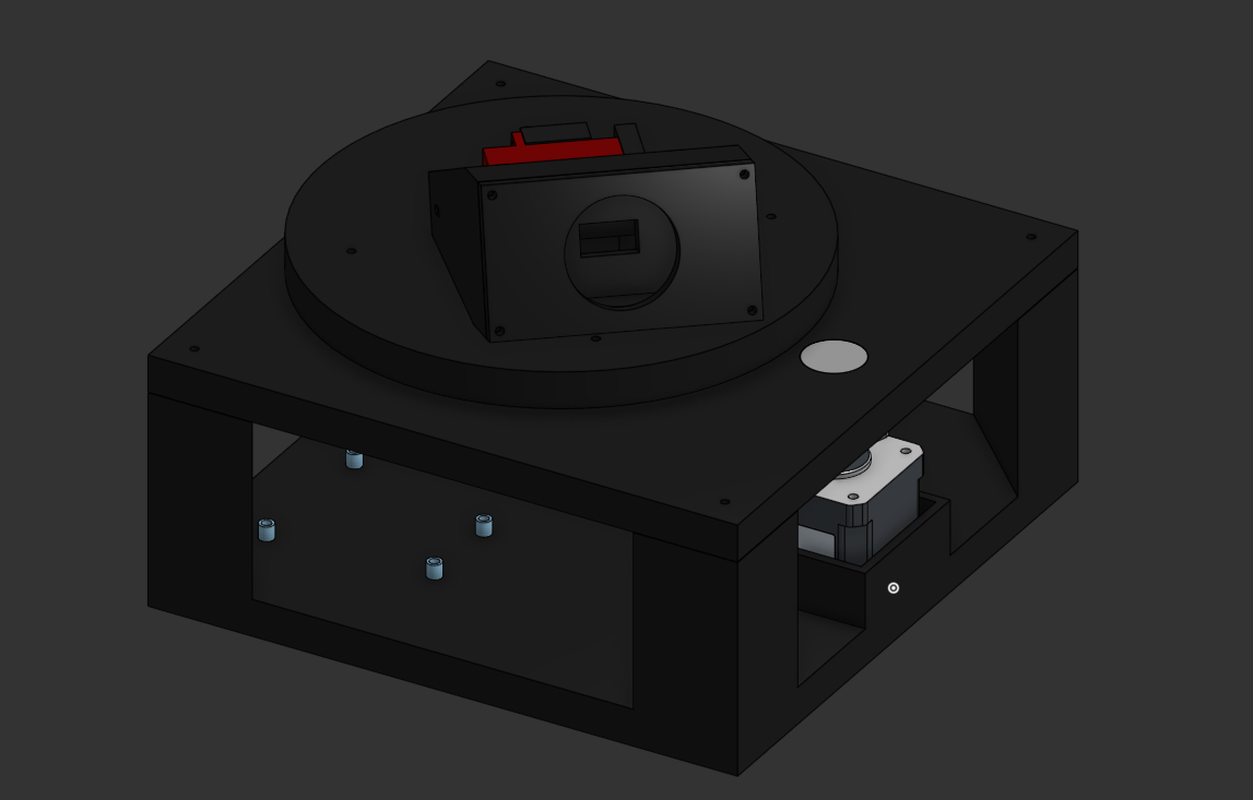
.\drone_detector\.venv\Scripts\python.exe .\drone_detector\live_tracker\demo_flight_simulations.py --scenario allI made the turret CAD in Onshape:
Open the turret CAD in Onshape
DroneDetection/
|-- README.md
|-- JOURNAL.md
|-- assets/
|   |-- demo_simulations/          # rendered simulation videos and GIFs
|   `-- project_photos/            # photos, screenshots, and PCB previews
|-- Drone PCB/                     # drone-frame board KiCad files, Gerbers, and STEP
|-- Turret Control PCB/            # turret controller KiCad files, Gerbers, and STEP
|-- drone_detector/
|   |-- live_tracker/              # camera tracking, 3D position, prediction, turret control
|   |-- pico_turret_platformio/    # Pico 2 turret firmware
|   |-- pico_drone_platformio/     # Pico 2 drone-control firmware
|   |-- pico_drone_controller/     # older MicroPython drone-control prototype
|   |-- esp32_drone_bridge/        # ESP32-C3 and BMI160 test work
|   |-- scripts/                   # Docker and workflow helper scripts
|   |-- train_yolov8.py
|   |-- evaluate_model.py
|   `-- run_tracker_sim.ps1
|-- dataset_toolkit/               # dataset scripts and reports
`-- archived/                      # older files I kept for reference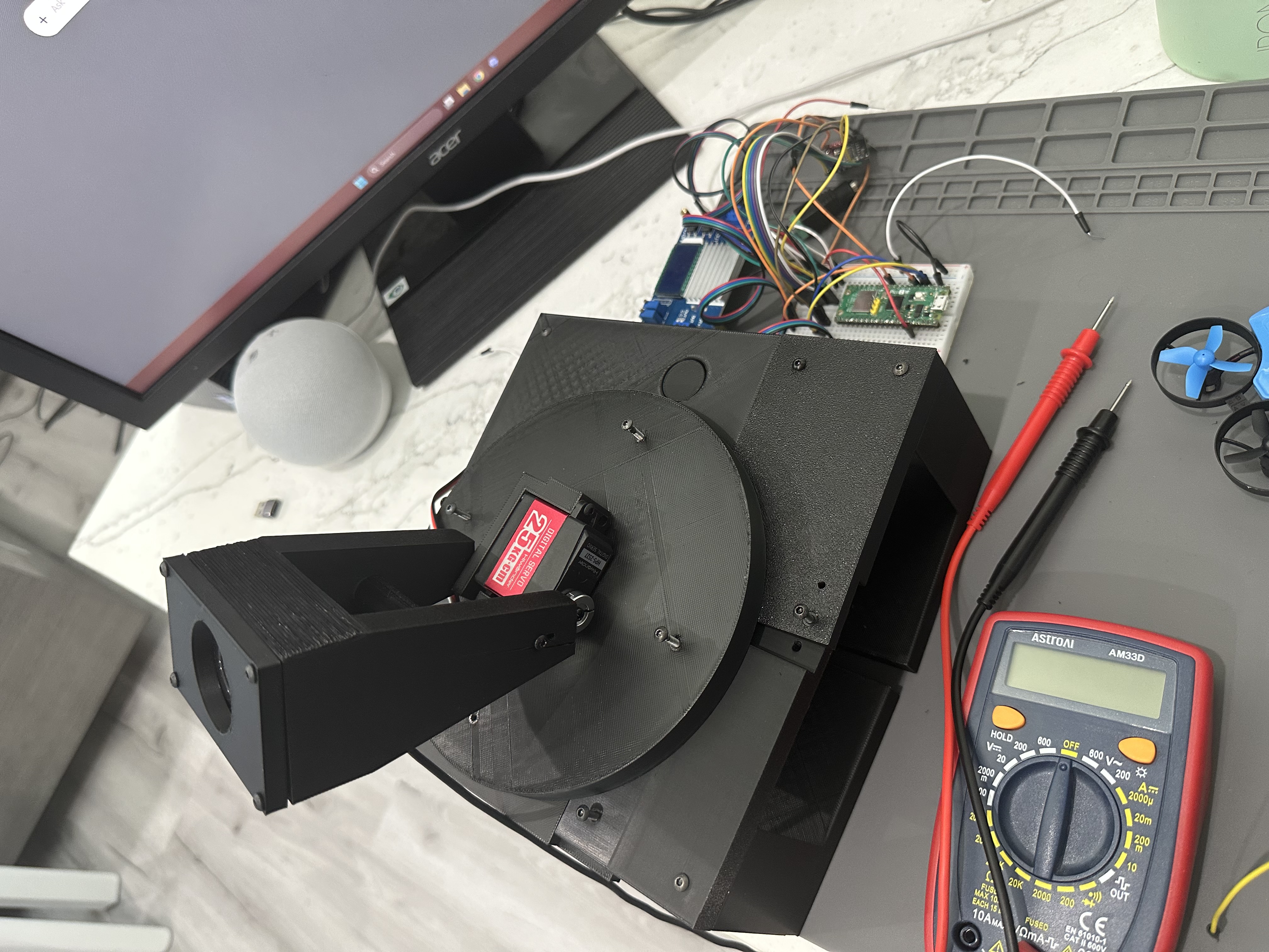
The turret uses:
I first tried controlling the drone by sending filtered voltage signals into the original controller. It kind of worked, but it was not clean enough. The original joystick circuit kept affecting the voltages, and I did not want the final version to depend on a hacked controller.
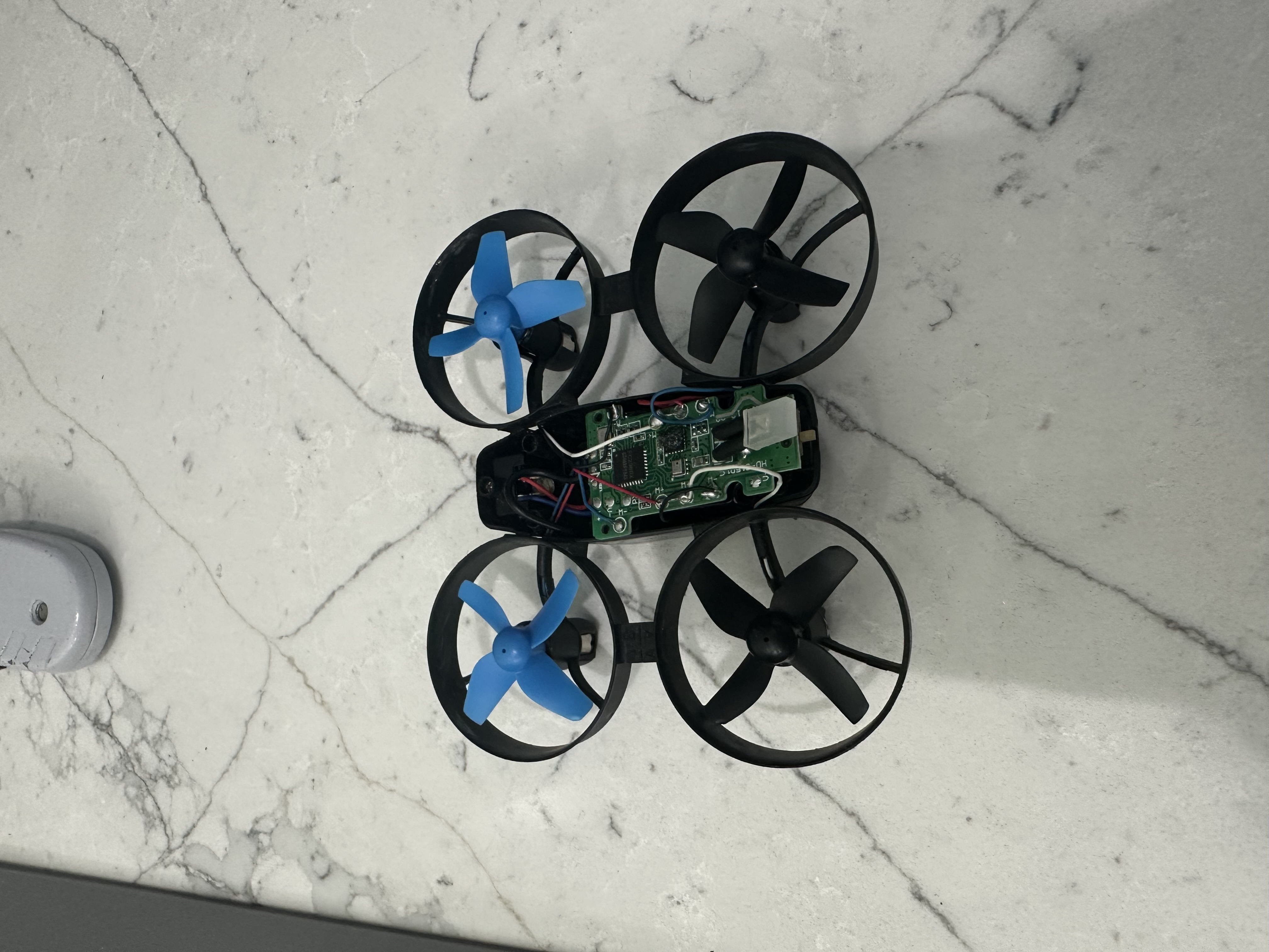
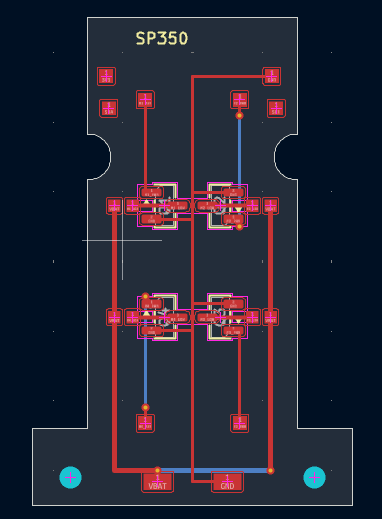
After that, I designed a custom board for the small SP350-style drone frame. The board is meant to reuse the frame, motors, and propellers, but make the electronics easier to understand and modify.
The drone PCB includes:
I used YOLO-format drone datasets and merged them into one dataset with one class: drone. The scripts can merge datasets, clean labels, preview annotations, train the model, and evaluate it.
Main scripts:
drone_detector/merge_roboflow_datasets.pydrone_detector/clean_dataset.pydrone_detector/preview_labels.pydrone_detector/train_yolov8.pydrone_detector/evaluate_model.pyThe tracker looks for this model first:
drone_detector/models/production_drone_model.ptIf it is not there, it tries this one:
drone_detector/models/drone_roboflow_best.ptdrone_detector/live_tracker/turret_tracker.py reads camera frames and runs YOLOv8. It picks the best drone box, finds the center of that box, and compares it to the center of the camera frame.
error_x = box_center_x - frame_center_x
error_y = box_center_y - frame_center_y
That error becomes the basic pan and tilt correction.
The camera is treated like the origin:
camera = (0.0, 0.0, 0.0) inchesThe tracker estimates:
x = left/right from the camera center
y = up/down from the camera center
z = forward distance away from the camera
Depth comes from the visible width of the drone in the camera image. The code uses the camera focal length, the expected drone width, and the bounding-box width to estimate distance. Then it uses the camera angle to turn that into x, y, and z.
The raw position jumps around because camera detections are noisy. I added filtering so one bad frame does not make the turret move too much.
The prediction code:
Current launcher defaults:
prediction horizon: 0.18 seconds
max prediction step: 14 inches
position smoothing alpha: 0.55
velocity smoothing alpha: 0.30
lost target hold: 0.15 secondsThe Python tracker sends simple USB serial commands to the Pico:
PAN <steps>
TILT <angle>
PANZERO
STATUS
STOP
Pan uses the horizontal pixel error. Tilt uses the vertical estimate and stays inside the servo limits. If the target disappears for a short moment, the turret holds the last filtered position instead of instantly snapping somewhere else.
The Pico firmware ramps the stepper speed at the start and end of a move:
slow start pulse delay -> fast cruise pulse delay -> slow ending pulse delayThis helped because the stepper was more likely to stall when it started too fast.
Run the tracker:
cd C:\Users\aptcs\Downloads\Projects\DroneDetection\drone_detector
.\.venv\Scripts\Activate.ps1
.\run_tracker_sim.ps1 -Port COM6 -Source 0
Use a lower pan gain if the turret overshoots:
.\run_tracker_sim.ps1 -Port COM6 -Source 0 -KpPan 0.40Emergency stop:
.\.venv\Scripts\python.exe -c "import serial,time; s=serial.Serial('COM6',115200,timeout=1); time.sleep(1); s.write(b'K\n'); s.flush(); time.sleep(.3); print(s.read(200).decode(errors='ignore').strip()); s.close()"Check Pico status:
.\.venv\Scripts\python.exe -c "import serial,time; s=serial.Serial('COM6',115200,timeout=1); time.sleep(1); s.write(b'STATUS\n'); s.flush(); time.sleep(.3); print(s.read(300).decode(errors='ignore').strip()); s.close()"cd C:\Users\aptcs\Downloads\Projects\DroneDetection\drone_detector\pico_turret_platformio
..\.venv\Scripts\python.exe -m platformio run -e rpipico2 --target uploadPut Roboflow YOLOv8 exports here:
drone_detector/data/roboflow_raw/Drone1
drone_detector/data/roboflow_raw/Drone2
drone_detector/data/roboflow_raw/Drone3
Run the local workflow:
cd C:\Users\aptcs\Downloads\Projects\DroneDetection\drone_detector
python preflight_check.py --fix-dirs
python preflight_check.py
python merge_roboflow_datasets.py
python clean_dataset.py
python preview_labels.py --split train --count 20
python preflight_check.py --smoke-train
Train and evaluate:
python train_yolov8.py --device auto
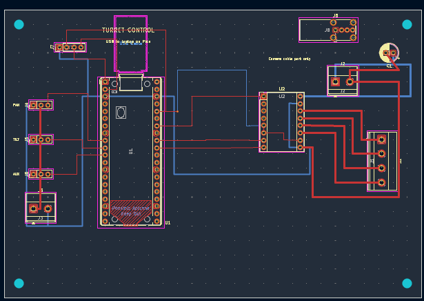
python evaluate_model.py --device autoBoth PCB folders include the KiCad project files, Gerbers/drill files, DRC reports, board previews, fabrication ZIPs, and STEP files.
| Board | Fabrication package | STEP file | Preview | Drive links |
|---|---|---|---|---|
| SP350 drone-frame PCB | SP350_PCB_fabrication.zip | Drone PCB.step | sp350_fc_compact.svg | Gerbers / Preview |
| Turret controller PCB | Turret_Control_PCB_fabrication.zip | Turret Control PCB.step | turret_control.svg | Gerbers / Preview |
The current DRC reports show 0 DRC violations and 0 unconnected pads for both boards.
The tracker prints lines like this while it runs:
[track] DETECT conf=0.82 err=(+74,-12) x=+8.4in y=+1.2in z=42.0in target_x=+8.4in target_y=+1.2in -> pico2 PAN +37 TILT 86Things I tuned while testing:
KpPan if pan is too slow.KpPan if the turret overshoots.deadband-x if it jitters near the center.imgsz for lower latency.imgsz if detections are unreliable.I designed, assembled, tested, and debugged this project. I also made the turret CAD.
The drone-frame prototype reuses the original Snaptain SP350-style frame, brushed motors, and propellers. Snaptain gets credit for those original commercial drone parts.
I used outside resources while learning about drone controls, PCB design, and simulation work, but the project idea, physical testing, wiring, debugging decisions, dataset work, CAD, and final integration choices are mine.
This project is for controlled tracking and electronics testing. When changing firmware, wiring, or control logic, test with the propellers removed or with the drone restrained.
| Qty | Value | Footprint | References |
|---|---|---|---|
| 5 | VBAT | B+, M1+, M2+, M3+, M4+ | |
| 2 | GND | B-, P2 | |
| 2 | NPTH | H1, H2 | |
| 1 | 3V3 | P1 | |
| 1 | M1 | Package_TO_SOT_SMD:SOT-23 | Q1 |
| 1 | M1PWM | P3 | |
| 1 | M1_LOW | M1- | |
| 1 | M2 | Package_TO_SOT_SMD:SOT-23 | Q2 |
| 1 | M2PWM | P4 | |
| 1 | M2_LOW | M2- | |
| 1 | M3 | Package_TO_SOT_SMD:SOT-23 | Q3 |
| 1 | M3PWM | P5 | |
| 1 | M3_LOW | M3- | |
| 1 | M4 | Package_TO_SOT_SMD:SOT-23 | Q4 |
| 1 | M4PWM | P6 | |
| 1 | M4_LOW | M4- | |
| 1 | SCL | P8 | |
| 1 | SDA | P7 |

dotnet/iot
This repo includes .NET Core implementations for various IoT boards, chips, displays and PCBs.

pascallanger/DIY-Multiprotocol-TX-Module
Multiprotocol TX Module (or MULTI-Module) is a 2.4GHz transmitter module which controls many different receivers and models.


rusefi/rusefi
rusefi - GPL internal combustion engine control unit

DraftShift/StealthChanger
Tool changing system for Vorons and other front mount printer motion systems, not just stealthburner.

VoronDesign/Voron-Hardware
Cool Hardware designed by the Voron Design group

hackclub/OnBoard
💡 Join 1,000 teenagers and make your first PCB with a $100 grant!

It measures 23 × 35 mm and has 2 copper layers, 1.6 mm thick.
24 parts. The full list of its parts is on this page, with links to each part's symbol and footprint where PCBKit's library has them.
From the aaravpatel0/DroneInterception repository on GitHub, at the commit this page was made from: the board is Drone PCB/Drone PCB.kicad_pcb and its schematic Drone PCB/Drone PCB.kicad_sch. PCBKit opens the board in the browser, with nothing to install.
Its repository states no licence, so its author keeps all rights: ask aaravpatel0 before reusing the design.